



Selden CXe 25 & CXe 45 — Owner's Manual

Packs, options, specifications, through-deck and bowsprit installation, electrical connection, operation, troubleshooting and maintenance of the Seldén CXe 25 and CXe 45 electric Code 0 furlers (OD on deck and TD through deck).
Download PDF ▾

CXe Electric Code 0 Furler
- Two-speed electric furler for Code sails; with a Seldén tack adaptor also for top-down furling gennakers. On deck (OD) or through deck (TD).
- Driven only by Seldén's 42V motor drive system (Power supply and SEL-Bus: manual 597-275-E). The controller monitors current and cuts out at a pre-set torque; sleep mode saves power.
- Anodized 6000-series aluminium, glass-fibre-reinforced UV-stabilised PC/PA; motor and reduction gear in an oil-filled, sealed housing, each unit pressure tested. TD: double seal between deck collar and drive unit.
- No brake or ratchet, no emergency furling function: not designed to store a permanently hoisted sail – always secure it with a strap or loop.
- Electrical work by a competent marine electrician; switch off before installation or service; never change the rated current of overcurrent protection; never leave the boat unattended with the CXe energized.
Basic Packs & Optional Parts
| Art. no. | Basic pack | Contents | |
|---|---|---|---|
| 545-455-18 | CXe25 OD | Drive unit 545-455-09, bag 596-196, deck connector kit 532-830-01, deck connector housing with support 532-842-01, manual | View part → |
| 545-455-28 | CXe25 TD | Drive unit 545-455-10, deck collar assembly 545-465-01, 2 insulators 530-778, 4 screws M8x40 153-008, manual | View part → |
| 545-455-20 | CXe45 OD | Drive unit 545-455-11, bag 596-196, deck connector kit 532-830-01, deck connector housing with support 532-842-01, manual | View part → |
| 545-455-30 | CXe45 TD | Drive unit 545-455-12, deck collar assembly 545-465-01, 2 insulators 530-778, 4 screws M8x40 153-008, manual | View part → |
| Part no. | Item | Description | Fits | |
|---|---|---|---|---|
| 545-207-01 | Halyard swivel | Included in extended packs | CXe 25 | View part → |
| 545-435-01 | Halyard swivel | Included in extended packs | CXe 45 | View part → |
| 405-501-01R | Block for 2:1 halyard | CXe 25, CXe 45 | View part → | |
| 508-844-01R | Dead-end fitting | CXe 25 | View part → | |
| 508-838-01R | Dead-end fitting | CXe 45 | View part → | |
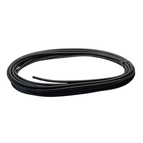
| 613-022-01 | AT cable Ø13 | 16000 / 19000 / 22000 / 25000 / 28000 mm | CXe 25 | View part → |
| 613-022-02 | AT cable Ø13 | 16000 / 19000 / 22000 / 25000 / 28000 mm | CXe 25 | View part → |
| 613-022-03 | AT cable Ø13 | 16000 / 19000 / 22000 / 25000 / 28000 mm | CXe 25 | View part → |
| 613-022-04 | AT cable Ø13 | 16000 / 19000 / 22000 / 25000 / 28000 mm | CXe 25 | View part → |
| 613-022-05 | AT cable Ø13 | 16000 / 19000 / 22000 / 25000 / 28000 mm | CXe 25 | View part → |
| 613-023-01 | AT cable Ø15 | 19000 / 22000 / 25000 / 28000 mm | CXe 45 | View part → |
| 613-023-02 | AT cable Ø15 | 19000 / 22000 / 25000 / 28000 mm | CXe 45 | View part → |
| 613-023-03 | AT cable Ø15 | 19000 / 22000 / 25000 / 28000 mm | CXe 45 | View part → |
| 613-023-04 | AT cable Ø15 | 19000 / 22000 / 25000 / 28000 mm | CXe 45 | View part → |
| 545-216-01 | Thimble kit | CXe 25 | View part → | |
| 545-416-01 | Thimble kit | CXe 45 | View part → | |
| 301-312-01 | AT clamp kit | CXe 25 | View part → | |
| 301-313-01 | AT clamp kit | CXe 45 | View part → | |
| 545-468-01 | Protective cage / anchor guard | CXe TD only | CXe 25, CXe 45 | View part → |
| 532-827-01 | SEL-Bus converter | For custom control buttons | CXe 25, CXe 45 | Ask us to source it → |
| 540-461-01 | Stainless panel | 1 push button | CXe 25, CXe 45 | Ask us to source it → |
| 540-462-01 | Stainless panel | 2 push buttons | CXe 25, CXe 45 | Ask us to source it → |
| 540-482 | Raised panel | CXe 25, CXe 45 | Ask us to source it → | |
| 532-830-01 | Deck connector kit | Included in OD basic packs | CXe 25, CXe 45 | Ask us to source it → |
| 532-842-01 | Deck connector housing with support | Included in OD basic packs | CXe 25, CXe 45 | Ask us to source it → |
AT cable lengths in order: 613-022-01 to -05 = 16000, 19000, 22000, 25000, 28000 mm; 613-023-01 to -04 = 19000, 22000, 25000, 28000 mm. Power supply and SEL-Bus parts (PSU, MCU, buttons, cables) are sold separately – order guide 597-283-E.
Technical Specifications
| CXe 25/45 | |
|---|---|
| Input voltage to motor control unit | 42V |
| Peak torque | 50 Nm |
| Peak current [42V] | 25A |
| Total gear ratio | 19:1 |
| Speed unloaded, low / high | 220 rpm / 500 rpm |
| Efficiency (MCU + drive unit) | 80% |
| Cable drive unit – MCU | 3x6 mm2, ø11,5 mm |
| Max service load | CXe 25: 25kN, CXe 45: 45kN |
| Main dimensions (mm) | CXe 25 | CXe 45 |
|---|---|---|
| Pin ø (D1) | 12 | 16 |
| Fork width (W1) | 21 | 22 |
| Fork depth (D2) | 32 | 34 |
| Width (W2) | 106 | 106 |
| Height (H1) | 285 | 300 |
| Width (W3) | 149 | 149 |
| Height (H2) | 140 | 140 |
| Width (W4) | 132 | 132 |
| T (deck thickness) | 50 | 50 |
CXe OD comes with a snap shackle that must go to a rigid point such as a pad eye. A soft attachment is not recommended (it can twist and fail); if unavoidable, keep it as short as possible so the motor unit cannot rotate.
Through Deck (laminate / wood)
- Deck must be 50 mm (2") thick at the two brackets and reasonably flat within the collar outline. Built-in angle 73°: AT-cable to deck must be 73°+-2° – check with a template and the halyard.
- Do not use the collar and bracket insulators (metal decks only). Deck must take the MSL.
- ø86 mm hole on the centreline (ø4-5 mm pilot). Deck >20 mm: extra hole 27 mm forward, hole-saw from below to depth = deck thickness-20 mm, remove the forward portion. Reduce thickness by 4 mm if cage 545-468 is used.
- Collar: tight fit (putty if needed); drill and tap four M8 or 5/16 holes, 15mm full thread (drill ~20 mm).
- Drive unit from below; brackets must mate fully, top of the unit slightly above the collar. Tap four M8 or 5/16 holes, 20 mm full thread min (drill ~25 mm).
- Clean, caulk round the hole, screws and loop, fit the collar. Fit both O-rings (thin grease), insert the unit without dislodging them, tighten screws with locking adhesive.
- Tools include ø86 mm hole saw or jigsaw, ø6.8 mm drill for M8, fiberglass putty, caulking, grease, threadlocker; M8 screws included (5/16" A4 alternatives: countersunk 1", cap screws 1 3/16").
Through Bowsprit (metal)
- Structure 44-48 mm thick at the brackets (44 mm with protective cage); weld nuts may replace tapped holes.
- ø88mm hole on the centreline; angle again 73°+-2°.
- Always fit the deck-collar and bracket insulators to prevent corrosion; corrosion-inhibiting compound on mating surfaces.
- Collar with insulator in the hole, drill and tap four M8 or 5/16 holes; drive unit from below, tap or drill clearance holes for nuts.
- Caulk the loop, fit O-rings (greased) and bracket insulators, insert the unit and tighten with locking adhesive.
Electrical Installation
- Deck contact: use the template supplied to check clearance (drive-unit cable is 5 m – do not exceed). Drill ø25 mm, tap five M6 holes (or suit 6 mm / 1/4" 316 screws).
- Route the cable, strip ~30 mm of outer insulation and ~13 mm of each conductor (cut and restart if the insulation is damaged). Dielectric grease on the strands, any terminal, grub screws tight; crimp terminals recommended, max ø 5 mm.
- Insert the socket in the housing; for left-hand operation turn the socket assembly 180°. Caulk, fit housing and support.
- Connector on the drive-unit cable: unscrew tail piece and body, push the lever to release the terminal, connect, then tighten tail piece and nut/grommet for a watertight joint.
- Connect the three black cables to MCU terminals L1, L2, L3 in any order. To reverse furling direction (e.g. UV strip on the other side), swap L1 and L2.
Operating
- Control current must be on. Low speed: push IN or OUT. High speed: while holding the first button, press the other.
- Unfurling: the motor must unfurl the sail, not the sheet or wind. Free the windward sheet; one turn of the leeward sheet on a winch, hand tension only; push OUT, then add IN for high speed; take up slack with light tension; release IN when almost unfurled, then OUT; trim only once fully unfurled.
- Furling: free the windward sheet, close-hauled is best; leeward sheet one turn on the winch with light tension; furl for a tight, even roll.
- Securing: always lock when unattended – TD: strap between the deck-collar loop and the thimble or fork; OD: strap through the bracket and the thimble or fork.
- Power loss: the system will not turn. Ease the sheet, get the sail behind the main and take it down; a large sail needs free water.
Troubleshooting & Care
| Problem | Cause | Action |
|---|---|---|
| Furler not operating | Electric failure or bad connection | Troubleshoot the electric system |
| Stops when heavily loaded | Overload: controller limits torque | Ease load and retry |
| Runs the wrong way | Wiring | Swap any two of the three motor cables |
| Oil leakage | Motor-unit seals or housing | Contact your Seldén representative |
| Grease leakage | Worm-gear seals or housing | Contact your Seldén representative |
- Rinse the whole system with fresh water, including a TD unit in an anchor box or bowsprit; check the anchor-box drain.
- Polish stainless parts, protecting black plastic; rinse off all detergent.
- Yearly: check for oil or grease leaks, protect aluminium with anti-corrosion spray, inspect the power cable and connections. Warranty 2 years.
Need a part that isn't listed? Ask us to source it and quote the part number from the PDF.
Products in this Manual
-


Selden 50 High Load Block (Halyard)
SEL40550101
$360.00 USDList Price: $420.00 USDUnit price /Unavailable -
Selden Head Swivel for CX25 Furlers
SEL545-207-01
$520.00 USDList Price: $604.00 USDUnit price /Unavailable -
Selden Anti Torsion Cable Clamps - 12 to 13 mm for CX25 Furlers
SEL301-312-01
$275.00 USDList Price: $317.00 USDUnit price /Unavailable -
Selden Thimbles for AT Cable: 15/32 - 1/2 in (12.0 - 13.0 mm) for CX25 Furlers
SEL545-216-01
$94.95 USDUnit price /Unavailable -
-
Selden Furlers - Anti-Torsion Cable for CX25 & GX15 - Dia: 1/2 in (13 mm) - 62.3 ft (19 m)
SEL61302202
$790.00 USDList Price: $917.00 USDUnit price /Unavailable -
Selden Dead-end Bracket for Code Zero Halyard, Max Rope ø14
SELDEN-DEAD-END-BRKT-C225-F305-MAX-ROPE-O14
$231.00 USDUnit price /Unavailable -
Selden Protective Cage / Anchor Guard for CXe25 & CXe45 Through Deck Furlers
SEL545-468-01
$395.00 USDUnit price /Unavailable -
Selden Anti Torsion Cable Clamps - 14 to 15 mm for CX45 Furlers
SEL301-313-01
$305.00 USDList Price: $352.00 USDUnit price /Unavailable -
Selden Thimbles for AT Cable: 9/16 - 5/8 in (14.0 - 16.0 mm) for CX45 Furlers
SEL545-416-01
$95.95 USDUnit price /Unavailable -

Selden AT-Cable (Anti-Torsion), ø15 mm, 28000 mm
SELDEN-AT-CABLE-BLACK-O15-28000
$1,620.00 USDList Price: $1,902.00 USDUnit price /Unavailable -
Selden AT-Cable (Anti-Torsion), ø15 mm, 25000 mm
SELDEN-AT-CABLE-BLACK-O15-25000
$1,440.00 USDList Price: $1,693.00 USDUnit price /Unavailable -
Selden AT-Cable (Anti-Torsion), ø15 mm, 22000 mm
SELDEN-AT-CABLE-BLACK-O15-22000
$1,270.00 USDList Price: $1,497.00 USDUnit price /Unavailable -
Selden AT-Cable (Anti-Torsion), ø15 mm, 19000 mm
SELDEN-AT-CABLE-BLACK-O15-19000
$1,100.00 USDList Price: $1,290.00 USDUnit price /Unavailable -
Selden AT-Cable (Anti-Torsion), ø13 mm, 28000 mm
SELDEN-AT-CABLE-BLACK-O13-28000
$1,150.00 USDList Price: $1,348.00 USDUnit price /Unavailable -
Selden Furlers - Anti-Torsion Cable for CX25 & GX15 - Dia: 1/2 in (13 mm) - 82 ft (25 m)
SEL61302204
$1,040.00 USDList Price: $1,206.00 USDUnit price /Unavailable -
Selden Furlers - Anti-Torsion Cable for CX25 & GX15 - Dia: 1/2 in (13 mm) - 72.2 ft (22 m)
SEL61302203
$910.00 USDList Price: $1,061.00 USDUnit price /Unavailable -
Selden Furlers - Anti-Torsion Cable for CX25 & GX15 - Dia: 1/2 in (13 mm) - 52.5 ft (16 m)
SEL61302201
$665.00 USDList Price: $772.00 USDUnit price /Unavailable -
Selden Dead-end Bracket for Code Zero Halyard, C280-F406, Max Rope ø16
SELDEN-DEAD-END-BRKT-C280-F406-MAX-ROPE-O16
$525.00 USDUnit price /Unavailable -
Selden Nail Terminal Kit for ø15 mm AT-Cable, CXr45, CX45, CXe45(includes 1 Terminal and 9 Nails)
SELDEN-NAIL-TERMINAL-KIT-NT-15-AT-CABLE-O15
$127.00 USDUnit price /Unavailable -
Selden Nail Terminal Kit for ø13 mm AT-Cable, CXr25, CX25, CXe25(includes 1 Terminal and 8 Nails)
SELDEN-NAIL-TERMINAL-KIT-NT-13-AT-CABLE-O13
$97.95 USDUnit price /Unavailable -
Selden Tackboard for Cableless Code - CXr45, CX45, CXe45
SELDEN-TACK-BOARD-45
$205.00 USDUnit price /Unavailable -
Selden Headboard for Cableless Code - CXr45, CX45, CXe45
SELDEN-HEAD-BOARD-45
$199.00 USDUnit price /Unavailable -
Selden Tackboard for Cableless Code - CXr25, CX25, CXe25
SELDEN-TACK-BOARD-25
$160.00 USDUnit price /Unavailable