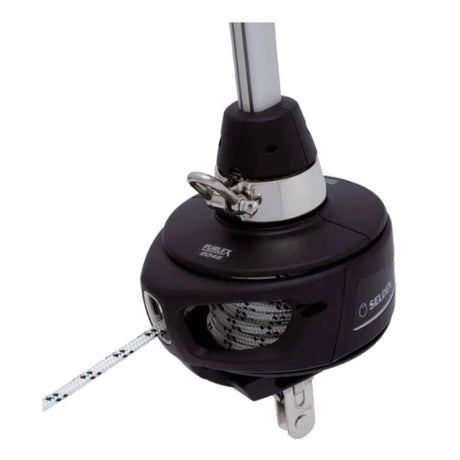




Selden Furlex 104S — Owner's Manual

Packs, dimensions, sail data, wire and extrusion length calculation, luff assembly, terminals, installation, operation, maintenance, troubleshooting and spare parts for the Seldén Furlex 104S jib furler (Ø4, Ø5 and Ø6 mm forestay).

Furlex 104S at a Glance
- Fourth-generation Furlex: uniform luff section to the tack, load-distributing ball races, compact halyard swivel on an HMPE loop, low-torque tack ring with "free turn" (soft-shackle ready), Aero grooves, third roller bearing in the drum unit, floating 316 connectors, air gaps at every join, removable swivels.
- Basic pack: drum unit, halyard swivel, furling rope, bearing halves, top guard, sail feeder, manual. Extended pack adds halyard leads, stanchion blocks and pre-feeder pack.
- Foil pack: luff extrusions, distance tubes, joining sleeves, connecting plates. Wire/eye pack: wire with swaged eye plus a stud/eye or Sta-lok eye terminal (with or without rigging screw).
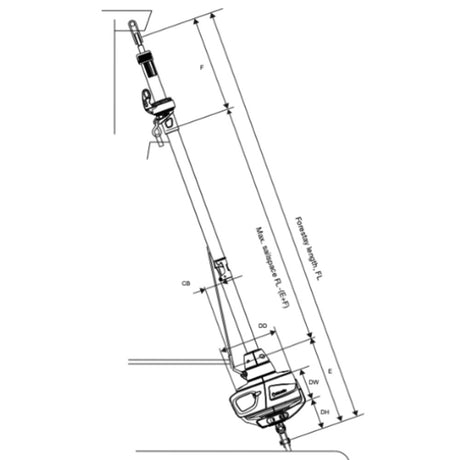
| Wire | DD | DH | DW | HO | Pin | TED | TET |
|---|---|---|---|---|---|---|---|
| Ø4 (5/32") | Ø155 | 85 | 65 | 40 | Ø8 | Ø8.5 | 4.5 |
| Ø5 (13/64") | Ø155 | 90 | 65 | 45 | Ø10 | Ø10.5 | 5.3 |
| Ø6 (15/64") | Ø155 | 100 | 65 | 55 | Ø10 | Ø12.5 | 7.0 |
Main dimensions in mm; inch values are in the PDF.
Safety
- Open the wire coil carefully – it can spring open.
- Never secure standing rigging with a snap shackle, even temporarily: use a screw-pin shackle or tie the halyard off.
- Halyard to forestay angle never less than 15° (15–20°) to avoid halyard wrap and shackle wear on the extrusion.
- Check for obstructions before using a winch on the furling line.
- Secure all split pins (20° separation).
Sail Data
| Ø4 & 5 | Ø6 | |
|---|---|---|
| Head deduction F | 440 (17 21/64") | 440 (17 21/64") |
| Tack deduction E (+ any toggle/link) | 205 (8 5/64") | 220 (8 21/32") |
| Cutback CB | 60 (2 23/64") | 60 (2 23/64") |
| Luff groove ø DLG | Ø6 (15/64") | Ø6 (15/64") |
| Luff groove width WLG | 2.75 (7/64") | 2.75 (7/64") |
| Luff extrusion | 30x20 (1 3/16" x 25/32") | 30x20 (1 3/16" x 25/32") |
Max sail space = FL – (F+E). Existing sails need luff length, Furlex-compatible luff tape and webbing loops at head and tack; a short sail gets an HMPE or wire pendant fixed to the head.
Wire & Top Extrusion Lengths
Slacken backstay/caps, pull the mast forward on a halyard tied off or on a D shackle (no snap shackles), lower the forestay and measure FL between the top swaged-eye hole and whatever lower part attached to the chain plate.
| Deduction | Ø4 mm | Ø5 mm | Ø6 mm |
|---|---|---|---|
| Lower terminal T, without rigging screw | 60 mm | 65 mm | 75 mm |
| Lower terminal T, with rigging screw | 147 mm | 150 mm | 155 mm |
| Fixed A+B, without rigging screw | 1260 mm | 1275 mm | 1290 mm |
| Fixed A+B, with rigging screw | 1175 mm | 1190 mm | 1210 mm |
- WL = FL – T – H (links or extra toggles). Example 104S/Ø5 with rigging screw 50% extended: 10 000 – 150 – 0 = 9850. For a swaged-stud stay, WL is the finished stay length, not a cutting length.
- N = (WL – (A+B)) / 2400, rounded down; C = N x 2400; top extrusion D = WL – (A+B) – C; top distance tube E = D – 200. Example: (9850-1190)/2400=3.6 → N=3, C = 7200, D = 1460, E = 1260.
- If D < 400 mm: Nnew = N-1, Cnew = Nnew x 2400 + 2000, Dnew = D + 400, Enew = E + 400. If D exceeds 2000 mm, cut it from a 2400 mm extrusion and leave out the 2000 mm one.
Luff Assembly (top down, on the wire)
- Stretch out the wire on a clean surface (protect any stud thread).
- Feed on the top extrusion and top distance tube (hinge sideways); push the tube in about half a joining sleeve with a short sleeve.
- Sta-lok systems: fit halyard swivel and top guard now (stud systems: after the sail feeder).
- Add each 2400 mm extrusion, distance tube and short sleeve; short connecting plate in the next extrusion, lock with the sleeve, connect, push the next tube on.
- Long joining sleeve, short distance tube and the 1000 mm extrusion (small-hole end first) with the long connector; push the short tube in approx. 40 mm.
- Snap on the sail-feeder connector and feeder; slide the swivel down onto it; push in the top guard and tighten its two screws to the bottom, not over-tight.
- Fit the bearing plug halves, forward hole aligned with the 1000 mm extrusion.
Terminals & Drum Unit
- Sta-lok eye: mark WL from the top eye centre, tape and cut; socket on, wedge over the 7-strand core with ~2 mm protruding, strands spaced evenly, bend in slightly, former in the terminal part, long bead of locking adhesive, tighten; check strands, then 2 or 3 more drops and tighten firmly.
- Stud/eye: remove the toggle, screw the eye onto the stud until the holes align, drive in the spirol pin.
- Drum unit: remove the two adaptor-half screws and the tube-shaft clevis pin, slide the unit over the eye terminal (flat faces on the ribs; rigging screw half unscrewed with all flats aligned), refit clevis and split pin, fit the adaptor halves (one way only) and tighten firmly, refit the toggle.
On the Boat
- Two people minimum, three recommended. Toggles at top and bottom for full articulation; the drum-unit toggle always goes directly to the chain plate.
- Halyard angle 15–20°: fit the two halyard leads (Extended Pack) or a sheave box if needed; replace leads at 50% wear. Keep the spinnaker halyard aft of the spreaders.
- First turning block at least 300 mm (11 13/16") from the drum. Raising the drum with an extension link needs a toggle between link and stemhead fitting. Below-deck/anchor-well installs: keep clear of the well, no deck conduit, big ball-bearing block, good drainage.
- Mast stepped: hoist the stay on a spare halyard with two taped clove hitches; go aloft in a proper bosun's chair. Mast down: lay the Furlex on the leading edge and watch it while craning.
Furling Line & Forestay Length
- Remove line guide and cover (loosen the underside screw and the two small screws, pull out the lock block). Pierce the rope 10-15 mm from the end, fit screw and washer with locking adhesive, refit.
- Wind approx. 30 turns by hand before hoisting. UV strip starboard = line exits port, and vice versa. Final cockpit block: self-aligning swivel, working load not less than 3000 N (300 kg/ 660lb).
- Rigging screw: sail down, halyard slack; remove the adaptor halves and drum clevis pin, slide the drum up and hold it, turn only the rigging-screw body, realign the flats, refit. Never remove the clevis pins that hold the forestay to the boat; do not force past the stop.
- Without rigging screw: lengthen with extra toggles; shorten by cutting wire and extrusion.
Hoisting & Furling
- Tension the forestay fully first; approx. 30 turns of line on the drum.
- Turn the tack ring counter-clockwise if the line exits port, clockwise if starboard (free-turn); tack to the shackle.
- Hoist in the starboard groove if the line exits port (and vice versa); tension to a vertical crease, then ease until it disappears; remove the pre-feeder.
- Furl tightly with tension on the leeward sheet; leave at least 3–5 turns on the drum.
- Check the swivel is at least 50 mm (1 31/32") below the top guard and the 15–20° angle; mark the halyard and backstay adjuster.
Reefing (close to beam reach): ease the sheet until the luff flaps, furl in while gradually easing, belay. Racing: remove line guide, cover and brims, lower the swivel to the drum for a twin-groove headfoil.
Checklist & Maintenance
- Halyard angle 15-20°; swivel at least 50 mm below the top guard; luff turns one turn before the tack ring; line guide clear of the flanges; free articulation top and bottom; split pins secured.
- Yearly: check the extrusion for damage, all rotating parts free; grease the four drum-unit bearings (remove the brims) and both halyard-swivel bearings with water-resistant Furlex grease.
- Wash with mild detergent and rinse; silicone-free polish on the extrusions; protect black plastic when polishing stainless.
- Store with the mast, no aluminium against steel, never wrapped damp in plastic; raise centre extrusions where it freezes.
- Never dismantle the halyard swivel or drum unit (loose balls) – dealer service. Warranty 2 years.
Troubleshooting
| Problem | Probable causes |
|---|---|
| Sail will not unfurl, or only partly | Halyard wrapped round the extrusion; halyard shackle/knot hitting the top extrusion (check 15-20°); furling line not free; forestay slack; dirt and salt in bearings; too much halyard tension |
| Sail will not furl or is hard to furl | Halyard wrap; no line on the drum; slack forestay; too much wind pressure; windward sheet held; free turn not working; sharp turning angles; line tangled on the drum; line guide chafing; swivel upside down |
| System wobbles | Forestay too loose |
| Sail unfurls after reefing | Not furled tightly or line not belayed |
| Hard to hoist | Luff tape too thick; sail caught; halyard routing; dirty groove |
| Luff cannot be tensioned | Swivel against the top guard or halyard angle too great |
| UV strip inside the roll | Line wound the wrong way (leave 3-5 turns when re-furled) |
| Wrinkles at the tack | Tack ring turned the wrong way before tacking |
Spares & Accessories
All items fit Ø4, Ø5 and Ø6 mm wire unless shown otherwise.
| Part no. | No. | Description | |
|---|---|---|---|
| 549-104-01R | 1 | Adapter assembly incl. screws | View part → |
| 549-125-01R | 2 | Top guard incl. screws | Ask us to source it → |
| 549-123-01R | 3 | Sail feeder | View part → |
| 549-119-01R | 4 | Lower bearing | View part → |
| 549-100-10R | 5 | Drum unit incl. shackle, clevis pin and split pin | Ask us to source it → |
| 549-111-01R | 6 | Lock block | Ask us to source it → |
| 549-109-10R | 7 | Cover assembly incl. lock block and screws | View part → |
| 549-107-01R | 8 | Brim assembly, two brims incl. screws | View part → |
| 549-116-01R | 9 | Halyard swivel incl. shackle | Ask us to source it → |
| 165-008-01R | 10 | Clevis pin and split pin | View part → |
| 307-086R | 11 | Screw pin shackle M8x16x32 | Ask us to source it → |
| 307-023R | 12 | Twisted screw pin shackle M8x16x32 | Ask us to source it → |
| 155-807-10R | 13 | Spare screw kit | View part → |
| 613-051-20R | 14 / 20 | Loop / strop HMPE Ø4 | View part → |
| 312-501 | 13 | Furlex grease ~100g | View part → |
| 612-034-12 | 14 | Furling line Ø8 L=20000 | Ask us to source it → |
| 538-971-01 | 15 | Stanchion block, 1-pack, for Ø25 | View part → |
| 505-538-01R | 16 | Prefeeder pack | View part → |
| 312-305 | 17 | Locking adhesive ~1g | View part → |
| 614-521R | 18 | Soft shackle 5 (3) mm | View part → |
| 549-127-10R | 19 | Connecting plate kit, 1 long + 5 short | View part → |
The accessories table restarts its numbering at 13 (as printed).

Wire, eye and luff extrusion packs
| Part no. | Item | Description | Wire | |
|---|---|---|---|---|
| 601-002-64 | – | Forestay wire pack L = 10500 | Ø4 | View part → |
| 601-003-64 | – | Forestay wire pack L = 10500 | Ø5 | View part → |
| 601-004-64 | – | Forestay wire pack L = 10500 | Ø6 | View part → |
| 601-003-65 | – | Forestay wire pack L = 12900 | Ø5 | View part → |
| 601-004-65 | – | Forestay wire pack L = 12900 | Ø6 | View part → |
| 601-052-64 | – | Forestay compact wire pack L = 10500 | Ø4 | View part → |
| 601-053-64 | – | Forestay compact wire pack L = 10500 | Ø5 | View part → |
| 601-054-64 | – | Forestay compact wire pack L = 10500 | Ø6 | View part → |
| 601-053-65 | – | Forestay compact wire pack L = 12900 | Ø5 | View part → |
| 601-054-65 | – | Forestay compact wire pack L = 12900 | Ø6 | View part → |
| 174-565-11 | 1 | Rigging screw pack | Ø4 | Ask us to source it → |
| 174-566-11 | 1 | Rigging screw pack | Ø5 | Ask us to source it → |
| 174-567-11 | 1 | Rigging screw pack | Ø6 | Ask us to source it → |
| 301-652-11 | 2 | Eye pack, stud | Ø4 | Ask us to source it → |
| 301-653-11 | 2 | Eye pack, stud | Ø5 | Ask us to source it → |
| 301-654-11 | 2 | Eye pack, stud | Ø6 | Ask us to source it → |
| 301-671-11 | 3 | Eye pack, sta-lok | Ø4 | Ask us to source it → |
| 301-672-11 | 3 | Eye pack, sta-lok | Ø5 | Ask us to source it → |
| 301-673-11 | 3 | Eye pack, sta-lok | Ø6 | Ask us to source it → |
| Part no. | Luff extrusion pack (wire Ø4-6) | |
|---|---|---|
| 549-132-02 | Luff extrusion pack, FL=8100 | View part → |
| 549-132-03 | Luff extrusion pack, FL=10500 | View part → |
| 549-132-04 | Luff extrusion pack, FL=12900 | View part → |
| 549-130-01 | Single pack: extrusion L=1000, joining sleeve L=250, distance tube L=865, connecting plate L=90 | View part → |
| 549-131-01 | Single pack: extrusion L=2000, joining sleeve L=200, distance tube L=1800, connecting plate L=40 | View part → |
| 549-132-06 | Single pack: extrusion L=2400, joining sleeve L=200, distance tube L=2200, connecting plate L=40 | View part → |
Toggles & Links
| Art. no. | Type | Wire | Length H | Pin / fork | |
|---|---|---|---|---|---|
| 174-102 | Eye/fork toggle | Ø 4 | 25 (1") | Eye 8, pin 8, fork 8 | Ask us to source it → |
| 174-103 | Eye/fork toggle | Ø 5 | 35 (1 3/8") | Eye 10, pin 9.5, fork 10 | Ask us to source it → |
| 174-104 | Eye/fork toggle | Ø 6 | 40 (1 1/2") | Eye 11, pin 11, fork 12 | Ask us to source it → |
| 517-056-02 | Fork/fork toggle | Ø 4 | 25 (1") | Pins 8 (165-113) / 8 (165-101); forks 7.5 / 8 | View part → |
| 517-054-02 | Fork/fork toggle | Ø 5 | 30 (1 3/16") | Pins 10 (165-221) / 10 (165-202); forks 10 / 11 | View part → |
| 517-046-02 | Fork/fork toggle | Ø 6 | 40 (1 1/2") | Pins 12 (165-409) / 10 (165-202); forks 11 / 11 | View part → |
| 517-944-01 | Eye/fork extension link | Ø 4 | 90 (3 9/16") | Pin 8, fork 7, hole 8.3, gauge 4 | View part → |
| 517-945-01 | Eye/fork extension link | Ø 5 | 90 (3 9/16") | Pin 10, fork 9.5, hole 10.3, gauge 4 | View part → |
| 517-063-01 | Eye/fork extension link | Ø 6 | 90 (3 9/16") | Pin 12, fork 11, hole 13, gauge 6 | View part → |
Need a part that isn't listed? Ask us to source it and quote the part number from the PDF.
Products in this Manual
-


Selden FOIL PACK FLX 104, FL=10500
SELDEN-FOIL-PACK-FLX-104-FL-10500
$525.00 USDUnit price /Unavailable -
Selden FOIL PACK FLX 104, FL=8100
SELDEN-FOIL-PACK-FLX-104-FL-8100
$435.00 USDUnit price /Unavailable -
Selden Compact ("Dyform") Wire with Eye Terminal, ø6 mm, Length 13 m, Furlex 100/104/204
SELDEN-CMP-PCK-FLX104-204-O6-13000
$207.00 USDList Price: $244.00 USDUnit price /Unavailable -
Selden Compact ("Dyform") Wire with Eye Terminal, ø5 mm, Length 12,9 m, Furlex 50/104
SELDEN-CMP-PCK-FLX104-O5-12900
$178.00 USDList Price: $209.00 USDUnit price /Unavailable -
Selden Compact ("Dyform") Wire with Eye Terminal, ø6 mm, Length 10,5 m, Furlex 100/104/204
SELDEN-CMP-PCK-FLX104-O6-10500
$173.00 USDList Price: $203.00 USDUnit price /Unavailable -
Selden Compact ("Dyform") Wire with Eye Terminal, ø5 mm, Length 10,5 m, Furlex 50/100/104S
SELDEN-CMP-PCK-FLX104-O5-10500
$150.00 USDUnit price /Unavailable -
Selden Compact ("Dyform") Wire with Eye Terminal, ø4 mm, Length 10,5 m, Furlex 50/100/104
SELDEN-CMP-PCK-FLX104-O4-10500
$98.95 USDUnit price /Unavailable -
Selden 19 Thread Standard Wire with Eye Terminal, ø6 mm, Length 13 m, Furlex 100/104/204
SELDEN-WIRE-PCK-FLX104-204-O6-13000
$220.00 USDUnit price /Unavailable -
Selden Standard 19 Thread Furlex Wire, ø5 mm X 12900 mm. Eye/Open End. Furlex Type A/50/100/104S
SELDEN-WIRE-PCK-FLX104-O5-12900
$132.00 USDUnit price /Unavailable -
Selden 19 Thread Standard Wire with Eye Terminal, ø6 mm, Length 10,5 m, Furlex 100/104/204
SELDEN-WIRE-PCK-FLX104-O6-10500
$157.00 USDUnit price /Unavailable -
Selden Standard 19 Thread Furlex Wire, ø5 mm X 10500 mm. Eye/Open End. Furlex Type A/50/100/104S
SELDEN-WIRE-PCK-FLX104-O5-10500
$115.95 USDUnit price /Unavailable -
Selden Standard 19 Thread Furlex Wire, ø4 mm X 10500 mm. Eye/Open End.Furlex 50/100/104S
SELDEN-WIRE-PCK-FLX104-O4-10500
$73.95 USDUnit price /Unavailable -
Selden Connecting Plate Kit, Furlex 104S
SELDEN-CONNECTING-PLATE-KIT-FLX-104
$45.99 USDUnit price /Unavailable -
Selden Soft Shackle, ø3 mm Dyneema Core, L=85 mm, Max Work Load 0,5 Ton
SELDEN-SOFT-SHACKLE-O5ROPE3-L-85
$42.99 USDUnit price /Unavailable -
Selden Locking Adhesive for Stalok Terminals
SELDEN-LOCKING-ADHESIVE-1ML
$23.99 USDUnit price /Unavailable -
Selden HMPE STROP L=330 ø4 (FLX104 HALY.SWIV.)
SELDEN-HMPE-STROP-L-330-O4-FLX104-HALY-SWIV
$20.99 USDUnit price /Unavailable -
Selden Spare Screws for Furlex 104S
SELDEN-SPARE-SCREW-KIT-FLX-104
$27.99 USDUnit price /Unavailable -
Selden Clevis Pin ø6x42 & Split Pin, Furlex 104S
SELDEN-CLEVIS-PIN-O6X42-SPL-PIN-F104
$19.99 USDUnit price /Unavailable -
-
Selden Cover Assembly, Furlex 104S
SELDEN-COVER-ASSEMBLY-FLX-104S
$97.95 USDUnit price /Unavailable -

Selden LOWER BEARING PLUG HALVES,F104
SELDEN-LOWER-BEARING-PLUG-HALVES-F104
$24.99 USDUnit price /Unavailable -
Selden SAIL FEEDER ASSY, FLX 104
SELDEN-SAIL-FEEDER-ASSY-FLX-104
$40.99 USDUnit price /Unavailable -
Selden Adaptor, Furlex 104S - 2-piece Connection Between Lower Swivel and the Luff Foil
SELDEN-FWD-AFT-ADAPT-HALVES-FLX104
$57.95 USDUnit price /Unavailable -
SEL03002067
$1,950.00 USDList Price: $2,516.00 USDUnit price /Unavailable