



Selden Furlex 50S — Owner's Manual

Assembly, halyard routing, sail sizing, operation, service and the complete illustrated spare-parts list for the Selden Furlex 50S jib furler (Ø4 and Ø5 mm forestays).
Download PDF ▾

This manual is split into 2 pages: Part 1 · Part 2 →
Kit Contents & Main Dimensions
In the Furlex box
- Forestay wire; halyard swivel with head shackle; lower bearing assembly with tack shackle; line guard unit; line guide fitting; lock block
- Furling line; 1 halyard lead (printed as 508-135) with 2 screws and insulating washer; drill bit Ø 5.3 mm; 1 stanchion block; prefeeder with rope; locking adhesive; grease; top guard incl. 1 screw
- Foil pack: 1 x 600 mm extrusion with join sleeve and distance tube, 1 x 2000 mm extrusion with distance tube, 2–4 x 2400 mm extrusions with distance tube + join sleeve, sail feeder + connector, 1 long connecting plate (600 mm extrusion) and 1 short plate per 2400 mm extrusion.
- Tools: flat screwdriver, hacksaw, 2 adjustable spanners, polygrip pliers, tape, file, waterproof marker, Torx keys T15, T20, T25, T30, 20 m steel tape, knife; for the halyard lead a heavy-duty TORX T30 screwdriver and drill.
Dimensions (mm)
| Wire dim. | DD | DH | DW | TED | TET |
|---|---|---|---|---|---|
| Ø 4 | Ø 120 | ~ 100 | 60 | Ø 8.2 | 4 |
| Ø 5 | Ø 120 | ~ 100 | Ø 10.2 | 4.5 |
DD / DH / DW = lower bearing assembly diameter, height and width; TED / TET = upper wire terminal hole and thickness. The model designation is on top of the line drum; the forestay wire size is marked on the ball-bearing socket (item B11).
| Sail data (50 S) | mm |
|---|---|
| Head deduction F | 360 |
| Tack deduction E (add any extra toggle or link) | 215 |
| Cutback CB | 25 |
| Internal diameter of luff groove DLG | 6 |
| Width of luff groove WLG | 2.6 |
| Overall extrusion dimensions | 22x15 |
| Max. sail space | FL – (F+E) |
Mast & Deck Attachment
- The forestay connections must articulate in all directions; in most cases fit a toggle between the Furlex stay and the forestay attachment.
- Masthead top fitting: always connect via a toggle. Selden triple combi 505-011 (fractional rig) with Ø 4 & Ø 5 mm wire, and Selden 0-22 (517-904): connect directly. T-terminal: use a T/fork toggle.
- The lower end has a fork toggle as standard and normally connects directly to the forestay fitting. An extended link/toggle does not give the required flexibility: always connect via a toggle. Split pins opened 20°.
- Below deck (anchor well): at least 250 mm to the first turning point of the furling line; tack as close to the deck as possible; the system must never touch the edge of the deck cut-out; drain the well; ball-bearing blocks with large sheaves. For large distances use a stainless strip or rod, always via a fork/fork toggle – not a short wire pendant.
| Part No. | Toggle type | Forestay | Length H | Pins / eye | Fork widths | |
|---|---|---|---|---|---|---|
| 174-102 | Eye / fork toggle | Ø4 | 25 | Eye Ø8, pin Ø8 | W2 8 | Ask us to source it → |
| 174-103 | Eye / fork toggle | Ø5 | 35 | Eye Ø10, pin Ø9.5 | W2 10 | Ask us to source it → |
| 517-056-02 | Fork / fork toggle | Ø4 | 25 | Pins Ø8 / Ø8 | W1 7.5 / W2 8.5 | View part → |
| 517-054-02 | Fork / fork toggle | Ø5 | 30 | Pins Ø10 / Ø10 | W1 10 / W2 11 | View part → |
| 174-127 | T / fork toggle | Ø4 | 60 | Pin Ø8 | W2 8 | Ask us to source it → |
| 174-128 | T / fork toggle | Ø5 | 70 | Pin Ø9.5 | W2 10 | Ask us to source it → |
| 517-065-01 | Stem ball / eye toggle + fork/fork toggle | Ø5 | 138 | Stem ball Ø26 (HB 8.5, R 10), pin Ø10 | W2 11 | View part → |
Toggles can be supplied by a Furlex dealer. Dimensions in mm.
Wire & Luff Extrusion Calculation
Table 1 – Forestay wire length
- Determine mast rake with fore- and backstay tensioned; slacken the backstay without touching the forestay rigging screw (or mark it); pull the masthead forward on the genoa halyard (D shackle or tied).
- Measure FL with just enough tension to keep it straight.
- T (lower wire terminal): 4 mm Ø wire – 45 mm; 5 mm Ø wire – 55 mm. Subtract the length H of any link or extra toggle.
- Example (Ø 5): FL 9,675 – 55 = WL 9,620.
Table 2 – Luff extrusion
- A+B fixed deduction: – 855 mm (both wire sizes).
- C = maximum number of 2400 mm (94 1/2") extrusions shorter than C+D.
- D = top extrusion, normally cut from the 2000 mm (78 3/4") extrusion; round the cut edges with a file.
- If D is shorter than 400 mm (15 3/4"), replace the uppermost 2400 mm extrusion with the 2000 mm one (joint moves down 400 mm): reduce C by 400 mm, increase D by 400 mm, and shorten its distance tube from 1900 mm to 1800 mm.
- E (top distance tube) = D – 120 mm.
- Example (Ø5): 9,620 – 855 = 8,765; C 7,200 (3 extrusions); D 1,565; E 1,445.
Assembly
Luff extrusion & wire
- On a horizontal surface, start from the lower bearing: long connecting plate (L=80 mm) in the 600 mm extrusion with join sleeve and distance tube.
- Take the join sleeve out of one 2400 mm extrusion (it is used later for the top extrusion), connect the 2400 mm extrusion and push the distance tube fully in so the sleeve enters the next extrusion.
- Connect the rest; each distance tube about 100 mm in (half a join sleeve), the top tube E about 20 mm in.
- Push on the lower bearing assembly and clamp it with the screw through the extrusion recess; tape the halyard swivel down at the sail-feeder area; fit the top guard and tighten its screw until it bottoms.
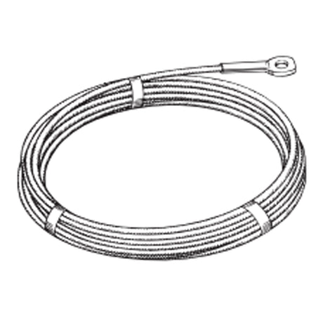
- Mark WL from the middle of the end hole (the wire has a burnt conical end – do not cut yet), unscrew eye, wedge and former, thread the wire down from the top until the eye stops on the top guard. Check ~ 40 mm between mark and terminal, tape and cut, deburr.
- Twist the strands (clockwise seen from below), fit the wedge with the strands protruding approx 2 mm, seat the strands, fit the former, long bead of locking adhesive, tighten; unscrew and check no strand is in the wedge slot; 2-3 drops of adhesive and tighten (permanent).
Line, sail feeder & line guard
- Feed the furling line through the line guide fitting and the hole in the lower drum flange; screw it into the recess under the drum with the screw head flush.
- Hook the sail feeder into the extrusion, push it to the joint sleeve and press the connector on from the front ("UP" mark).
- Fit the line guard over the terminal with the lock block ("UP" mark), fit the line guide fitting and set the guard midway between the drum flanges; align the line guide with the lead block.
- Load about 25 turns on the drum by turning the extrusion: clockwise if the UV strip is on starboard (line exits to port), anti-clockwise if on port.
- Stanchion block (Ø25 mm stanchion or pulpit, ball-joint): set so the line leaves the forestay at right angles, lock with the M6 screw and the self-tapping screws. Final swivel block by the cockpit: maximum working load not less than 2500 N. (575lb.); belay on a normal cleat when leaving the boat.
Halyard Routing & Leads
- The halyard-to-forestay angle must be 5–10°; less risks halyard wrap, which can damage halyard, extrusion and forestay and put the rig at risk.
- One bronze halyard lead is in the kit (spare lead set 508-159-03). Fit the self-adhesive insulating washers between lead and mast to avoid galvanic corrosion. Drill with the Ø 5.3 mm bit using the lead as template; grease the self-tapping M6 screws. Fit a lead "over" each genoa halyard.
- Figs. 5.4.c–5.4.e in the PDF give the mounting dimensions for Selden masts (masthead and triple-combi fractional rigs); on other makes check the angle carefully – too large an angle adds friction and wear. Inspect leads yearly; replace at 50% wear (not covered by the guarantee).
- Alternatively fit a sheave box (below). Keep the spinnaker halyard clear: lead it around the upper shroud and down aft of the spreaders.
| Part No. | Sheave box | Halyard wire | Max. rope | Sheave width | |
|---|---|---|---|---|---|
| 505-061-02 | C-35 | Ø 3 | Ø 8 | 10 mm | View part → |
| 505-004-10 | AL-45 | Ø 4 | Ø 12 | 13 mm | Ask us to source it → |
| 505-072-03 | C-45 | Ø 4 | Ø 12 | 13 mm | View part → |
Adapting the Sail
- Max luff = FL – (F+E). Use webbing loops at head and tack; luff tape to suit the 22x15 extrusion.
- Keep at least 20 mm (3/4") between the top of the halyard swivel and the top guard with the sail fully tensioned.
- Pendant length: attach the head directly to the swivel, tack the sail at deck level with a rope to the tack shackle, hoist and adjust the rope until the swivel reaches its top position with the 5–10° angle; measure the rope and talurit-splice a wire pendant of that length to the head.
Sailing with Furlex
Hoisting
- Tension forestay/backstay for close-reach sailing before hoisting.
- Flake the sail with the tack forward, tie the pre-feeder line, attach tack and sheet.
- Luff tape through the pre-feeder, head to the swivel shackle, halyard to the swivel's rope lashing; hoist through the sail feeder.
- Tension until a vertical crease appears, then ease; remove the pre-feeder.
- Furl tightly; 3–5 turns must remain with the largest sail furled. Check 20 mm (3/4") swivel clearance and the 5–10° angle, then mark the halyard and backstay adjuster.
- Never tension the halyard when the sail is reefed or furled.
Unfurling, furling & reefing
- Unfurl with a turn of the line on a winch or half a turn on a cleat for drag; best between close reach and beam reach.
- Furl with light tension on the leeward sheet; belay on a cleat; stow the sail or use a furling tube for long lay-ups.
- Reef on a close reach: ease the sheet until the luff flaps, pull in the line, belay. Best shape: unfurl completely, then reef down.
- Adjust the sheeting point when reefed (a low-clew genoa needs it sooner than a high-clew jib).
- Forestay length: lengthen with extra toggles (one standard toggle H=35 mm moves the masthead 125 mm aft on a nominal 10600 mm Ø 5 mm stay). Never shorten by removing the lower Furlex toggle.
Maintenance & Dismantling
Service & storage
- Remove the sail, empty the drum, flush with fresh water and dry; brush the kit grease into lower bearing points A and B and halyard swivel points C and D.
- Off the boat: wash with mild detergent, rinse thoroughly, silicon-free polish on the extrusion.
- Store with the mast; never wrapped while damp; in frost areas store dry or with the centre higher than the ends.
- Rigging: tension the forestay to 20% of the wire's breaking strain, about 15% of the backstay's on a masthead rig (forestay = about 1.25 x backstay tension).
Dismantling
- Do not dismantle the halyard swivel or lower bearing assembly (uncaged loose balls).
- Sail feeder: tape it, lever off the connection piece with a screwdriver, lift out the feeder.
- Line guide: roll off the line (count the turns), loosen screws, remove the line guide fitting downwards, keep the lock block.
- Forestay: remove toggle and eye (heat to 100° C if the adhesive holds), remove the former, refit the eye at least 3 turns and hit it hard along the stay to free the cone; cut strands about 5 mm in, prise off the wedge. Fit a new Sta-Lok wedge on reassembly.
- A 5 mm shorter forestay moves the masthead 11 mm forward on a 10600 mm stay; compensate with 5% more tension (permanent tension max 20% of breaking strain) or an eye/fork toggle.
- Luff: push the 600 mm distance tube up about 100 mm and hook it out (inner diameter about 6 mm), then unhook each extrusion.
Troubleshooting
| Problem | Probable cause | Action |
|---|---|---|
| Cannot be unfurled | Halyard wrap; furling line not free; forestay too slack; dirt and salt in bearings; halyard strain | Ease and roll back; free the line; tension backstay or shorten the system; flush and grease; ease the halyard |
| Will not furl / hard to furl | Halyard wrap; no line on the drum; slack forestay; wind pressure; windward sheet not released; tangled sheet; large line angles; dirt | Add line (at least 5 turns left when fully furled); tension the forestay; ease the leeward sheet; re-route the line; flush and grease |
| System "wobbles" | Forestay too loose | Tension forestay and/or backstay |
| Unfurls after reefing | Not furled tightly / line not belayed | Furl with drag; belay the line |
| Hard to hoist | Luff tape too thick; sail caught; halyard routing; dirty groove | Sailmaker per table 7.1.1; clear the sail; check sheaves; clean the groove |
| Luff cannot be tensioned | Swivel contacts the top guard; halyard angle too great | Have the luff shortened or move the halyard lead up |
| UV strip inside the roll | Line wound the wrong way | Empty the drum and rewind the right way |
| Leech flogs / closes | Sheeting point; leech line; old sail | Move the sheeting point forward / aft; consult the sailmaker |
Need a part that isn't listed? Ask us to source it and quote the part number from the PDF.
Products in this Manual
-

-

SEL02201554
$1,030.00 USDList Price: $1,337.00 USDUnit price /Unavailable -
Selden Lubricating Grease (90 g) - for Furlex, Winches and Furling Masts
SELDEN-LUBRICATING-GREASE-TUBE-90-G
$20.99 USDUnit price /Unavailable -
SEL02201552
$970.00 USDList Price: $1,248.00 USDUnit price /Unavailable -
SEL02201551
$870.00 USDList Price: $1,125.00 USDUnit price /Unavailable -

-
Selden Forestay Wire (10.5m - 4mm) for 100S Furlers
SEL-SPR-601-002-30
$131.00 USDUnit price /Unavailable -
Selden FOIL PACK FLX 50(MK2),FL=12500
SELDEN-FOIL-PACK-FLX-50MK2-FL-12500
$450.00 USDUnit price /Unavailable -
Selden FOIL PACK FLX 50(MK2),FL=10100
SELDEN-FOIL-PACK-FLX-50MK2-FL-10100
$375.00 USDUnit price /Unavailable -
Selden FOIL PACK FLX 50(MK2), FL=7700
SELDEN-FOIL-PACK-FLX-50MK2-FL-7700
$295.00 USDUnit price /Unavailable -
Selden LINE GUIDE FITT. ASSY FLX 50
SELDEN-LINE-GUIDE-FITT-ASSY-FLX-50
$50.95 USDUnit price /Unavailable -
Selden LINE GUARD BRKT ASSY FLX 50
SELDEN-LINE-GUARD-BRKT-ASSY-FLX-50
$173.00 USDUnit price /Unavailable -
SEL02201555
$1,150.00 USDList Price: $1,491.00 USDUnit price /Unavailable -
SEL02201553
$940.00 USDList Price: $1,216.00 USDUnit price /Unavailable -
Selden Composite Sheave Box with ø45 mm Composite Sheave - M6 Screws Included
SELDEN-SHEAVE-BOX-O45X13-155-613-SCREW-FIX-COMP
$69.95 USDUnit price /Unavailable -
Selden Composite Sheave Box with ø35 mm Composite Sheave - Screws Included
SELDEN-SHEAVE-BOX-O35X10-ASSY-171-007-SCR-FIX
$42.99 USDUnit price /Unavailable -
Selden Stemball/eye Toggle with Jaw/jaw Toggle, for ø5 mm Headstays
SELDEN-TOGGLE-STEMBALL-FORK-WIRE-5
$141.00 USDUnit price /Unavailable -
Selden Aluminium Luff Section, 2400 mm, Furlex 50S
SELDEN-LUFF-EXTR-ASSYCON-22-15-2400
$169.00 USDUnit price /Unavailable -
Selden Connecting Plate (45x7 mm) for Furlex 50S Foil System
SELDEN-CONN-SPRING-FLX-50-45X7-ST
$7.99 USDUnit price /Unavailable -
Selden Aluminium Luff Section, 2000 mm, Furlex 50S
SELDEN-LUFF-EXTR-ASSY-22-15-2000
$163.00 USDUnit price /Unavailable -
Selden Connecting Plate (80x7 mm) for Furlex 50S Foil System
SELDEN-CONN-SPRING-FLX-50-80X7-ST
$7.99 USDUnit price /Unavailable -
-
Selden SAILF. 35x16 FLX 50 (MK2) ST
SELDEN-SAILF-35X16-FLX-50-MK2-ST
$24.99 USDUnit price /Unavailable -
Selden LUFF EXTR.L=600,FLX50(MK2) AL
SELDEN-LUFF-EXTR-L-600-FLX50MK2-AL
$68.95 USDUnit price /Unavailable