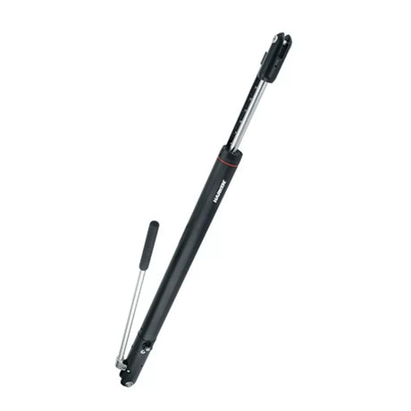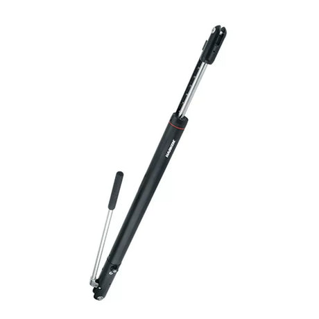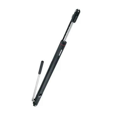
Harken Hydraulic Integral Backstay Adjuster — User Manual

Sizes and factory-set pull forces, installation, bleeding, operation and service for the Hydraulic Integral Backstay Adjuster.
Download PDF ▾

Specifications
| Part no. | Size | Max wire | Stroke | Pin center length (closed) | Weight | Gap / pin Ø | Max pull force | |
|---|---|---|---|---|---|---|---|---|
| HCI006BCC | -6 | 5.5 mm (7/32") | 360 mm (14.7") | 762 mm (30") | 3.79 kg (8.36 lb) | 11.1 mm (7/16") | 1710 kg (3770 lb) | View part → |
| HCI010BCC | -10 | 7 mm (9/32") | 360 mm (14.7") | 762 mm (30") | 3.79 kg (8.36 lb) | 12.7 mm (1/2") | 2136 kg (4710 lb) | View part → |
| HCI012BCC | -12 | 8 mm (5/16") | 360 mm (14.7") | 762 mm (30") | 4.41 kg (9.72 lb) | 15.9 mm (5/8") | 3043 kg (6710 lb) | View part → |
| HCI017BCC | -17 | 9.5 mm (3/8") | 360 mm (14.7") | 762 mm (30") | 4.41 kg (9.72 lb) | 15.9 mm (5/8") | 3808 kg (8390 lb) | View part → |
For boats 9–18 m (30–60'). Pin center length open = closed length plus stroke. Weights include the rod-end forks. Relief valves are factory-set to the pull force shown; setting them higher can cause overloading and may void the warranty. Built-in single-acting pump, position indicator. A standard eye/jaw toggle is ordered separately.
Installation
- Tools: 3 mm hex driver, blue Loctite 242.
- To measure: open the release knob fully counterclockwise, attach the end clevis to the deck and the rod clevis to the main halyard, and pull it fully open. There is no built-in return force.
- Include the toggle length when deducting the adjuster length from the stay.
- Fit an eye/jaw toggle on the bottom clevis so the clevis does not fatigue; mount rod end up, pump handle where you want it.
- Attach lower clevis to toggle, toggle to chainplate, extend, then upper clevis to the backstay. Blue 242 Loctite on the screws.
Bleed and Operate
- Bleed: vertical, rod end up, fully extended; open the release valve and pump the handle for one minute.
- Increase tension: close the release knob clockwise, hand tight only (no pliers), then pump.
- Decrease: turn the knob counterclockwise; release speed depends on how far it is opened. The knob rests closed.
- Ease the jib halyard before tensioning: the backstay can overload the jib halyard, luff and furler.
- The handle can be locked with the roll pin H-84814 or left off and inserted when needed.
Hydraulic adjusters exert very high loads. Inspect all backstay and forestay components before use. The cylinder is pressurized: do not disassemble; service only by Harken-authorized personnel.
Maintenance
- Inspect visually before each use.
- Clean visible areas with soap and water and rinse with fresh water.
- No regular maintenance if properly bled and kept clean. Change seals every ten years (depending on use), or sooner if the adjuster eases without the relief valve opening.
| Part no. | Description | |
|---|---|---|
| H-85275 | Position indicator assembly (fibreglass) | View part → |
| H-84814 | Handle roll pin | Ask us to source it → |
Parts in this Manual We Carry
Harken part numbers as printed in the user manual, matched to the genuine parts in our store.
Need a part that isn't listed? Ask us to source it and quote the part number from the PDF.
Products in this Manual
-

-

HARHCI006BCC
$2,305.95 USDList Price: $2,620.30 USDUnit price /Unavailable -
HARHCI010BCC
$2,305.95 USDList Price: $2,620.30 USDUnit price /Unavailable -
HARHCI012BCC
$2,527.95 USDList Price: $2,872.65 USDUnit price /Unavailable