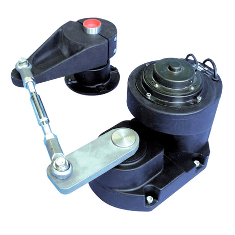
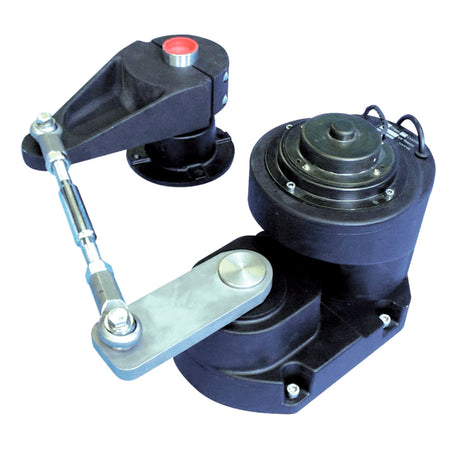
Lewmar Direct Drive Autopilot Drive — Installation Guide

Drive selection data, mounting, draglink and tiller-lever geometry, course-computer wiring, post-installation checks and maintenance for the Lewmar Direct Drive autopilot drives (89300037 to 89300050) on boats with mechanical steering.

Drive Specifications
| Part No. | Description | Tiller lever length | HP | Volts | No load speed (RPM, as printed "RMP") | Max rudder torque ft lbs | Max rudder torque MKG | Average current | Breaker motor | Breaker clutch | Weight kg / lb | Guide to boat size |
|---|---|---|---|---|---|---|---|---|---|---|---|---|
| 89300037 | Direct 1/8hp 12v DL 166mm OL | 10" | 1/8 | 12 | 10 | 988 | 138 | 4A | 16A | 1.5A | 8 / 17.6 | Up to 11.6m (38') |
| 89300038 | Direct 1/8hp 12v DL 134mm OL | 8" | 1/8 | 12 | 10 | 988 | 138 | 4A | 16A | 1.5A | 8 / 17.6 | Up to 11.6m (38') |
| 89300039 → | Direct 1/4hp 12v DL 166mm OL | 10" | 1/4 | 12 | 10 | 1794 | 248 | 4A | 16A | 3A | 9 / 19.8 | Up to 16.75m (60') |
| 89300040 → | Direct 1/4hp 12v DL 134mm OL | 8" | 1/4 | 12 | 10 | 1794 | 248 | 4A | 16A | 3A | 9 / 19.8 | Up to 16.75m (60') |
| 89300041 | Direct 1/4hp 24v DL 166mm OL | 10" | 1/4 | 24 | 10 | 1794 | 248 | 2.5A | 10A | 2A | 9 / 19.8 | Up to 16.75m (60') |
| 89300042 | Direct 1/4hp 24v DL 134mm OL | 8" | 1/4 | 24 | 10 | 1794 | 248 | 4A (as printed) | 10A | 2A | 9 / 19.8 | Up to 16.75m (60') |
| 89300043 | Direct 1/4hp 2412v DL 166mm OL | 10" | 1/4 | 24/12 | 10 | 1794 | 248 | 2.5/4A | 10A | 3A | 9 / 19.8 | Up to 16.75m (60') |
| 89300044 | Direct 1/4hp 2412v DL 134mm OL | 8" | 1/4 | 24/12 | 10 | 1794 | 248 | 2.5/4A | 10A | 3A | 9 / 19.8 | Up to 16.75m (60') |
| 89300045 | Direct 1/2hp 24v DL 166mm OL | 10" | 1/2 | 24 | 10 | 3080 | 426 | 3.5A | 16A | 2A | 10.5 / 23.1 | Up to 24.4m (80') |
| 89300046 | Direct 1/2hp 24v DL 134mm OL | 8" | 1/2 | 24 | 10 | 3080 | 426 | 3.5A | 16A | 2A | 10.5 / 23.1 | Up to 24.4m (80') |
| 89300047 | Direct 1/2hp 2412v DL 166mm OL | 10" | 1/2 | 24/12 | 12 | 3080 | 426 | 3.5A | 16A | 3A | 10.5 / 23.1 | Up to 24.4m (80') |
| 89300048 | Direct 1/2hp 2412v DL 134mm OL | 8" | 1/2 | 24/12 | 12 | 3080 | 426 | 3.5A | 16A | 3A | 10.5 / 23.1 | Up to 24.4m (80') |
| 89300049 | Direct 1/2hp 24v DL | 1/2 | 24 | 17 | 3080 | 426 | 3.5A | 16A | 2A | 10.5 / 23.1 | Up to 24.4m (80') | |
| 89300050 | Direct 1/2hp 2412v DL | 1/2 | 24/12 | 17 | 3080 | 426 | 3.5A | 16A | 3A | 10.5 / 23.1 | Up to 24.4m (80') |
"DL" = draglink, "OL" = output lever (166 mm or 134 mm centres). The Maximum Output Torque columns are blank in the manual. 89300049 and 89300050 are listed without an output lever length.

Preparation
- In the box: Direct Drive, draglink, M8 securing bolts with washers and lock-nuts.
- You also need a secondary tiller lever and lever pins: get them before you start.
- The drive is not waterproof: mount it in a dry place clear of bilge water, accessible for service.
- It produces considerable force: mount it on a substantial frame member (build a frame if needed), never on structure that supports cabins (noise and vibration).
- It can be mounted in any attitude on a vertical or horizontal surface, facing either way; steering direction is corrected by reversing the motor polarity at the course computer.
- Keep the drive and its cables at least 3ft (1m) from VHF equipment and cables, 7ft (2m) from SSB.
Mounting and Geometry
- Fix the drive with M8 bolts, washers and lock-nuts; connect the draglink to the drive and to the tiller lever or quadrant.
- The gearbox can be mounted flat or inverted, from 200mm to 2000mm from the rudderstock.
- Figure A (Cobra or Mamba, extended primary tiller lever): work to the offset of 128mm ± 5mm; keep the drive body parallel to the tiller lever axis.
- Figure B (independent secondary tiller): any angle and distance round the stock, drive parallel to the tiller lever; set the offset angle from distance L (table).
- Figure C (under deck, linked to the Cobra pedestal output lever): use the shorter 134mm output lever for 1:1 geometry.
- Figure D: as Figure A, but on a tiller quadrant.
- The tiller lever must move 36° port and starboard.
| (L) Distance between Direct Drive centre and rudder stock | Offset angle Ø |
|---|---|
| 200 – 225 | 25° |
| 226 – 250 | 23° |
| 251 – 300 | 20° |
| 301 – 350 | 17° |
| 351 – 400 | 14° |
| 401 – 500 | 12° |
| 501 – 750 | 10° |
| 751 – 1000 | 8° |
| 1000+ | 5° |
Connecting to the Course Computer
- Switch the power off before making any connection.
- Drive motor: two single-core black cables, twisted as a pair in sleeving. Clutch: two-core cable, brown (+) and blue (-).
- Measure the total cable run to the course computer and size the motor cable from the table below; use at least 1.5mm2 (14 AWG) copper for the clutch.
- Join with connectors or junction boxes of the correct rating, route following the EMC guidelines, then connect: clutch brown to +ve, blue to -ve; either motor core to either motor terminal (reverse later if the rudder moves the wrong way).
Post-Installation Checks
- Drive secured to a substantial structure?
- Tiller lever moves 36° port and starboard?
- Most suitable drive output lever used?
- Motor and clutch cables correctly routed and secure at the course computer?
Maintenance
- Regularly check that all connections and mountings are secure.
- Check the draglink connections.
- Check the cables for wear or damage.
Need a part that isn't listed? Ask us to source it and quote the part number from the PDF.
Products in this Manual
-


Lewmar Direct Drive Unit 166 mm OL (1/4 hp - 12V)
LEW89300039
$3,860.00 USDList Price: $6,002.95 USDUnit price /Unavailable -
Lewmar Lever O-P 166 - Direct Drive
LEW85000661
$108.95 USDList Price: $158.95 USDUnit price /Unavailable -
Lewmar Direct Drive Unit 134 mm OL (1/4 hp - 12V)
LEW89300040
$3,670.00 USDList Price: $5,716.95 USDUnit price /Unavailable