Lewmar S900 / S2000 Gen 2 Stern Windlass — Owner's Manual

Specifications, bulkhead installation, auto-stop set-up, cable sizing, freefall and powered operation, servicing and the spares kits for the Lewmar S900 and S2000 Gen 2 stern (rope) windlasses, plus the drill template and the earlier S900/S2000 manual.
Download PDF ▾

Specifications
| Model | Rope Ø | Supply | Motor | Working load limit | Normal current | Circuit breaker | Weight |
|---|---|---|---|---|---|---|---|
| S900 | 12–16 mm 1/2"–5/8" |
12 V | 600 W | 200 kg 440 lb |
85 A | 90 A | 11.6 kg 26 lb |
| S2000 | 12–16 mm 1/2"–5/8" |
12 V | 1000 W | 420 kg 924 lb |
100 A | 110 A | 19.9 kg 44 lb |
The gypsy is designed for leaded lines of 12 to 16 mm diameter.
Bulkhead Preparation
- Choose a position at the stern in line with the anchor roller: the lead from the roller must feed straight back to the pulley and along its centre line.
- Minimum bulkhead thickness 25 mm (1"). The supplied M8 screws suit bulkhead plus packing of 25–30 mm (1"–1 3/16"); source longer M8 countersunk screws for thicker bulkheads.
- Foam or balsa-cored bulkheads need reinforcement to spread the recovery torque. Fit a pad if the bulkhead is not flat.
- Allow clearance behind the bulkhead for the motor/gearbox and at least 300 mm (12") of vertical fall for the line at all times, or it will jam.
- Tools: marine sealant, drill with 9 mm (3/8") bit, 50 mm (2") hole saw, 5 mm (3/16") Allen key, 13 mm (1/2") spanner, crimping tool.
Fitting
- Using the template, drill 4 × 9 mm holes for the M8 mounting screws and cut one 50 mm hole for the rode; seal the cut edges.
- Tighten the M8 screws to 21 Nm (5 mm Allen key, 13 mm spanner).
- Secure the mounting plate with M10 screws to 43 Nm (8 mm Allen key, 17 mm spanner).
- Position the 4 gearbox mounting bolts with their hex heads in the housing recesses for the motor/gearbox position you want; secure the main unit with 4 × M8 screws to 21 Nm (6 mm Allen key).
- Key in the driveshaft, slide the motor/gearbox on and secure with 4 × M8 nuts and washers to 21 Nm.
- Loading the rode: pass it through the bulkhead roller, pull back the control arm, lead it round the gypsy and down the bottom channel of the rope guide into the locker; release the arm, secure the bitter end, power in the rest.
Auto-Stop Sensor & Brass Coil
- Isolate the windlass. Fit the sensor to its bracket, feed the cable through the housing grommet and keep it clear of moving parts and the falling rode.
- With the anchor just below the water, set the sensor within 6 mm of the rode and mark the rode above the sensor.
- Stow the anchor, cut power, and fit the brass wire coil at the mark: pierce the rope, push the wire through and fold it along the rope, wind the free end 8 times round the rope and over the other end, knot and twist the ends, trim to about 5 mm and tuck under the wrap. The wrap's outside diameter should almost match the rope's.
- Lower a few metres and haul in: the windlass stops as the anchor breaks the water; pulse it to stow. Re-adjust the sensor height or coil as the rode stretches, and replace the coil when the sheave wears it.
- On installation, check the motor direction: UP must be up, and it must stop when the sensor connects.
Electrical Wiring
| Model | Supply | Normal current | Breaker | 0–7 m (0–23 ft) | 7–15 m (23–50 ft) | 15–22 m (50–73 ft) |
|---|---|---|---|---|---|---|
| S900 | 12 V | 85 A | 90 A | 16 mm² / 6 AWG | 25 mm² / 4 AWG | 35 mm² / 2 AWG |
| S2000 | 12 V | 100 A | 110 A | 16 mm² / 6 AWG | 25 mm² / 4 AWG | 35 mm² / 2 AWG |
- Cable lengths are the total run from the battery along the cable route; do not confuse cable length with boat length. Voltage drop over the run must not exceed 10%.
- Fully insulated system, type III stranded tinned copper with copper crimp terminals. Check polarity.
- Fit the supplied breaker close to the battery in a dry, accessible place; it must be reset manually after a trip.
- Multi-station: all switches wired in parallel. The wiring diagrams (S900 and S2000 drawn separately) show a 3 A fuse on the control circuit.
| Part no. | Electrical item | |
|---|---|---|
| 68000349 | Circuit breaker 90 A, supplied with S900 | View part → |
| 68000350 | Circuit breaker 110 A, supplied with S2000 | View part → |
| 68000593 | Guarded rocker switch (supplied) | View part → |
| 68001213 | Contactor assembly, S900 (supplied) | Ask us to source it → |
| 68001214 | Contactor assembly, S2000 (supplied) | Ask us to source it → |
| 68000967 | Wireless remote, 3 button (windlass only), optional | View part → |
| 68000968 | Wireless remote, 5 button (windlass & thruster), optional | View part → |
| 68001357 | Remote handheld control, optional | Ask us to source it → |
| 68001289 | Y splitter, optional | Ask us to source it → |
Manual Controlled Freefall
- Isolate the windlass. Press the plunger button on the drive cap until it stays down, then release the anchor line.
- Insert the Lewmar handle in the drive cap: clockwise grips the gypsy, anticlockwise frees it to control the rate of descent.
- Once deployed, lock the clutch clockwise, engage the anchor locks and remove the handle.
- To return to powered operation, pull the locking button out to disengage the plunger.
Power Up / Down
- Plunger disengaged (up). Release the anchor line and engage the breaker.
- Press DOWN for 2 seconds until the anchor freefalls. Holding DOWN over 5 seconds lengthens the clutch re-engagement on the next UP.
- When enough line is out, press UP continuously until freefall stops; it takes several seconds to re-engage and lock the internal clutch. Unlocked, the rope can creep out.
- Press UP continuously to retrieve.
- Never use the windlass as a mooring bollard: secure the rode to a cleat or other strong point.
Servicing
Schedule
- Bedding-in: check electrical connections and mounting screws frequently while new.
- After use: fresh-water wash; rode at least 12" (300 mm) below the windlass; check the locker drain and the rode.
- Annually (or more often): connections, mounting screws, rode wear, and the gypsy – a high-wear item.
Gypsy Replacement
- Isolate and secure the rode. Remove the drive cap screw and washer (Loctite®-sealed; may need warming).
- Hold the plunger in and unscrew the freefall mechanism (left-hand thread on a starboard windlass).
- Remove the stripper screws, pull the control arm clear, move the stripper and lift off the gypsy, noting the rope-tooth direction.
- Clean without solvent or wire brush, lubricate the freefall plunger, lightly grease mating faces on reassembly.
- Keep Loctite® off the driveshaft thread or freefall will not work. Tighten the stripper screws then back off 1/2 turn so the stripper lies loose on the gypsy.
Troubleshooting
| Problem | Check / remedy |
|---|---|
| Rode pays out when not in use | Rope not secured and drive cap slack: tighten the drive cap with the handle and always secure the rope independently |
| Failure to operate or sluggish | Mostly electrical. A 12 V system should hold 13.5 V; constant low voltage damages the motor. Check cable size, switches, connections, battery, isolator, fuse and motor |
| Failure to operate | Voltage at contactor and switch inputs (breaker, fuses); voltage at the solenoid switch terminal when operated (else switch/wiring); voltage at the contactor main output (else coil ground, then contactor); at least 12.5 V at the motor and no rotation = motor defective |
Spares Kits

Gen 2 (ref B17416)
| Kit no. | Description | Items included (qty) | |
|---|---|---|---|
| 66000842 | Gen 2 port control arm kit | 7(1), 17(1), 18(1), 19(1), 21(1) | Ask us to source it → |
| 66000843 | Gen 2 stbd control arm kit | 36(1), 17(1), 18(1), 19(1), 21(1) | Ask us to source it → |
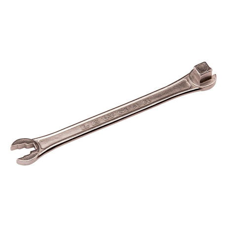
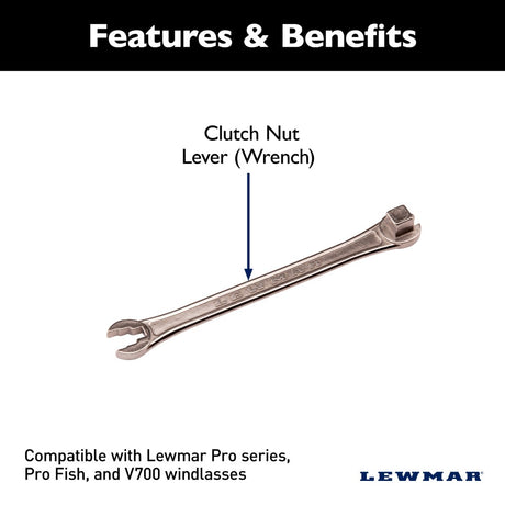
| 66000099 | Clutch lever | 20(1) | View part → |
| 66000833 | Gen 2 port drive cap | 16(1) | Ask us to source it → |
| 66000832 | Gen 2 stbd drive cap | 37(1) | Ask us to source it → |
| 66000834 | Gen 2 bulkhead unit | 22(1), 44(4) | Ask us to source it → |
| 66000835 | Gen 2 mounting bracket kit | 8(1), 32(2), 35(4) | Ask us to source it → |
| 66000844 | Gen 2 port stopper cam / rope guide kit | 6(1), 10(1), 33(1), 35(4) | Ask us to source it → |
| 66000845 | Gen 2 stbd stopper cam / rope guide kit | 38(1), 6(1), 33(1), 35(4) | Ask us to source it → |
| 66000810 | Gypsy | 23(1) | Ask us to source it → |
| 66000811 | Stripper kit | 11(1), 28(2) | Ask us to source it → |
| 66000836 | Gen 2 port drive cone kit | 3(1), 12(1), 27(1), 39(1) | Ask us to source it → |
| 66000837 | Gen 2 stbd drive cone kit | 40(1), 41(1), 3(1), 27(1) | Ask us to source it → |
| 66000839 | S900 port driveshaft kit | 1(1), 5(1), 13(1), 15(1) | Ask us to source it → |
| 66000838 | S900 stbd driveshaft kit | 42(1), 1(1), 5(1), 13(1) | Ask us to source it → |
| 66000841 | S2000 port driveshaft kit | 1(1), 4(1), 43(1), 13(1) | Ask us to source it → |
| 66000840 | S2000 stbd driveshaft kit | 4(1), 9(1), 1(1), 13(1) | Ask us to source it → |
| 66001190 | Autostop | 24(1) | Ask us to source it → |
| 66000816 | S900 motor / gearbox | 25(1), 35(4), 29(4), 31(4), 34(4) | Ask us to source it → |
| 66000817 | S2000 motor / gearbox | 26(1), 35(4), 29(4), 31(4), 34(4) | Ask us to source it → |
Earlier S900/S2000 (ref B10500)
| Kit no. | Description | Items included (qty) | |
|---|---|---|---|
| 66000097 | Control arm kit | 7(1), 17(1), 18(1), 19(1), 21(1) | View part → |
| 66000099 | Clutch lever | 20(1) | View part → |
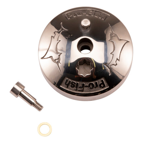
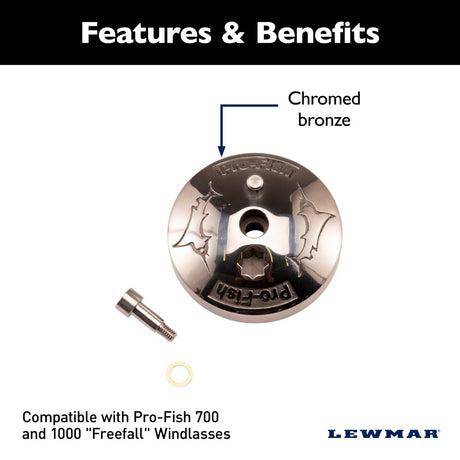
| 66000620 | Pro-Fish drive cap | 16(1) | View part → |
| 66000807 | Bulkhead unit | 23(1) | Ask us to source it → |
| 66000808 | Mounting bracket kit | 8(1), 14(1), 30(3), 31(3), 32(3), 33(1), 36(3) | Ask us to source it → |
| 66000809 | Stopper cam / rope guide kit | 6(1), 10(1), 34(1), 35(4) | Ask us to source it → |
| 66000810 | Gypsy | 24(1) | Ask us to source it → |
| 66000811 | Stripper kit | 11(1), 29(2) | Ask us to source it → |
| 66000812 | Drive cone kit | 3(1), 12(1), 28(1) | Ask us to source it → |
| 66000813 | 600 W driveshaft kit | 1(1), 5(1), 13(1), 15(1) | Ask us to source it → |
| 66000814 | 1 kW driveshaft kit | 1(1), 4(1), 9(1), 13(1) | Ask us to source it → |
| 66001190 | Autostop | 25(1) | Ask us to source it → |
| 66000816 | 600 W motor / gearbox | 2(4), 22(4), 26(1), 37(4) | Ask us to source it → |
| 66000817 | 1 kW motor / gearbox | 2(4), 22(4), 27(1), 37(4) | Ask us to source it → |
Item numbers refer to the exploded view of each edition; the two editions number their parts differently.
Drill Template
Bulkhead drill template for the mounting screw holes and the 50 mm rode hole. Download the PDF and print it at 100% (1:1, no "fit to page"), then check a dimension with a ruler before drilling.
Need a part that isn't listed? Ask us to source it and quote the part number from the PDF.
Products in this Manual
-


Lewmar 3-Button Windlass Remote Kit
LEW68000967
$360.00 USDList Price: $602.95 USDUnit price /Unavailable -
Lewmar Pro-Fish Drive Cap Assembly Kit
LEW66000620
$184.00 USDList Price: $279.95 USDUnit price /Unavailable -
Lewmar Pro Series & V700 Clutch Lever Kit
LEW66000099
$20.99 USDList Price: $31.95 USDUnit price /Unavailable -
Lewmar 5-Button Windlass & Thruster Wireless Remote Kit
LEW68000968
$490.00 USDList Price: $817.95 USDUnit price /Unavailable -
LEW68000593
$74.95 USDList Price: $121.95 USDUnit price /Unavailable -
Lewmar Winch Circuit Breaker - 110 Amp w/Panel
LEW68000350
$115.95 USDList Price: $182.95 USDUnit price /Unavailable -
-
Lewmar Winch Circuit Breaker - 90 Amp w/Panel
LEW68000349
$115.95 USDList Price: $182.95 USDUnit price /Unavailable