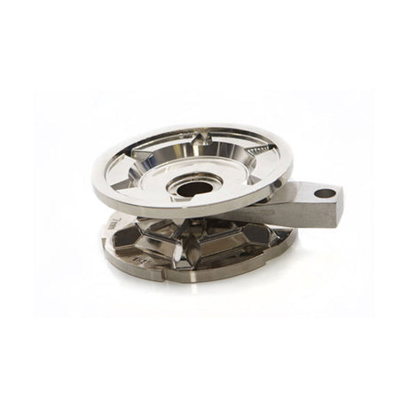
Lewmar V1-V6 Vertical Windlass — Owner's Manual

Performance, gypsy selection, deck and below-deck preparation, cable and breaker sizing, wiring, operation, servicing and the full kit lists for the Lewmar V1, V2, V3, V4, V5 and V6 vertical windlasses.
Download PDF ▾

Electric Specifications
| Model | V | Motor W | Typical max. pull | Max. line speed | Typical working load | Normal current draw (A) | Weight gypsy only | Weight gypsy/drum | Breaker |
|---|---|---|---|---|---|---|---|---|---|
| V1 | 12 | 700 | 750 kg 1653 lb |
28 m/min 92 ft/min |
188 kg 414 lb |
112 | 19 kg / 42 lb | – | 90 A |
| V1 MO | 12 | 700 | 750 kg 1653 lb |
28 m/min 92 ft/min |
188 kg 414 lb |
112 | 19 kg / 42 lb | – | 90 A |
| V2 | 12 | 700 | 850 kg 1874 lb |
29 m/min 95 ft/min |
213 kg 470 lb |
121 | 19 kg / 42 lb | 22 kg / 48.5 lb | 90 A |
| V2 | 24 | 900 | 850 kg 1874 lb |
29 m/min 95 ft/min |
213 kg 470 lb |
60 | 19 kg / 42 lb | 24.5 kg / 54 lb | 50 A |
| V3 | 12 | 1000 | 1025 kg 2260 lb |
39 m/min 128 ft/min |
257 kg 567 lb |
131 | 21.5 kg / 47 lb | 24.5 kg / 54 lb | 110 A |
| V3 | 24 | 1000 | 1025 kg 2260 lb |
39 m/min 128 ft/min |
257 kg 567 lb |
74 | 21.5 kg / 47 lb | 36 kg / 79 lb | 90 A |
| V4 | 12 | 1600 | 1250 kg 2750 lb |
25 m/min 82 ft/min |
313 kg 688 lb |
125 | 29 kg / 64 lb | 36 kg / 79 lb | 150 A |
| V4 | 24 | 2000 | 1500 kg 3306 lb |
27 m/min 90 ft/min |
375 kg 825 lb |
70 | 29 kg / 64 lb | 38 kg / 84 lb | 110 A |
| V5 | 12 | 2000 | 1450 kg 3190 lb |
27 m/min 90 ft/min |
363 kg 798 lb |
120 | 31 kg / 68 lb | 38 kg / 84 lb | 150 A |
| V5 | 24 | 2000 | 1600 kg 3520 lb |
29 m/min 97 ft/min |
400 kg 880 lb |
60 | 31 kg / 68 lb | 63 kg / 139 lb | 110 A |
| V6 | 24 | 2000 | 1800 kg 3960 lb |
16 m/min 52 ft/min |
450 kg 990 lb |
60 | 60 kg / 132 lb | – | 150 A |
The V1–5 gypsies are designed for Lewmar rope/chain rodes (rope spliced to a chain tail); the V6 is chain only. Rope must be windlass-grade, medium-lay nylon.
Gypsy Sizing
| Part no. | Gypsy, chain and rope | |
|---|---|---|
| 68000840 | V1/2/3 gypsy & stripper kit 006: 6mm ISO 4565, 1/4" G40*, 1/4" BBB; rope 12–14 mm (1/2") 3-strand and 8-plait | View part → |
| 68000360 | V1/2/3 gypsy & stripper kit 000: 7mm ISO 4565, 1/4" G40*, 1/4" BBB; rope 12–14 mm (1/2") 3-strand and 8-plait | View part → |
| 68000361 | V1/2/3 gypsy & stripper kit 001: 8mm DIN 766, 8mm ISO 4565; rope 12–16 mm (1/2–5/8") 3-strand, 8-plait 5/8 only | View part → |
| 68000362 | V1/2/3 gypsy & stripper kit 002: 10mm DIN 766, Campbell 3/8" S4, 5/16" G40; rope 12–16 mm (1/2–5/8") 3-strand, 8-plait 5/8 only | View part → |
| 68000363 | V1/2/3 gypsy & stripper kit 003: 10mm ISO, Campbell 3/8" S3, Lewmar 9.5mm G40; rope 16 mm (5/8") 3-strand and 8-plait | View part → |
| 68000356 | V4/5 gypsy 201: 8mm DIN 766, 8mm ISO 4565, 5/16" G40, 5/16" Campbell S4; rope 12–14 mm (1/2") 3-strand medium lay | View part → |
| 68000357 | V4/5 gypsy 202: 10mm DIN 766, 5/16" Campbell S3, 3/8" Campbell S4, 9.5mm G30; rope 16 mm (5/8") 3-strand medium lay | View part → |
| 68000358 | V4/5 gypsy 203: 10mm ISO 4565, 3/8" Campbell S3, Lewmar 9.5mm G40; rope 16 mm (5/8") 3-strand medium lay | View part → |
| 68000359 | V4/5 gypsy 204: 12mm ISO 4565, 13mm DIN 766; rope 18–20 mm (3/4") 3-strand medium lay | View part → |
| 68000903 | V6 gypsy (chain only): 10mm DIN 766, 3/8" ISO G4, Lewmar 9.5mm G40 | View part → |
| 68000904 | V6 gypsy (chain only): 11mm Short Link, Lewmar 12mm G30/G40, 13mm DIN 766, 7/16" G40; remote chain pipe version recommended | View part → |
| 68000905 | V6 gypsy (chain only): Lewmar 14mm G30/G40, 14mm DIN 766 | View part → |
| 68000906 | V6 gypsy (chain only): 1/2" ISO G4, Lewmar 12mm G30/G40, Lewmar 1/2" G30/G40 | View part → |
* as printed in the gypsy table. Chain from other makers can vary: check pitch (P), wire diameter (D) and width (W) against the chart below.
Deck & Tools
- V1–3: 10 mm (3/8") and 14 mm (9/16") drills, 75 mm (3") hole saw. Minimum deck 25 mm (1"); M8 studs suit deck plus packing of 25–50 mm (1"–1 31/32"); optional extended version for decks up to 127 mm.
- V4–5: 12 mm (7/16") drill, 77 & 90 mm (3" & 4 1/2") hole saw. Minimum deck 40 mm (1 1/2"); M10 studs suit 40–66 mm (1 1/2"–2 1/2").
- V6: 5 mm (3/16") and 12 mm (7/16") drills, 115 mm (4 1/2") hole saw. Minimum deck 40 mm (1 1/2"); M10 studs suit 40–56 mm (1 1/2"–2 1/4").
- Thin, foam or balsa-cored decks need reinforcement. V1–3 and V6 may need a pad for camber or sheer; on V4–5 a pad must keep the base parallel to the motor/gearbox flange (shim before fitting the motor).
- Lead from the bow roller must arrive horizontally at the top of the gypsy, on its centre line within ±5°, with enough vertical fall below (300 mm / 12" shown). Too little fall causes jamming.
- V1–3 motor/gearbox rotates 360 degrees on the Fast Fit clamp; V4–5 bolts via the through-deck bolts; V6 bolts to the base via a down tube. Keep it out of the chain fall.
Fitting Sequence
- Holes: V1–3 five 10 mm (3/8") holes for studs and sensor and two 75 mm (3") holes; V4–6 five 12 mm (7/16") holes and two 115 mm (4 1/2") holes (as printed). Seal the cut edges.
- Screw the studs into the base until they bottom out, flats nearest the windlass base.
- V1–5: lay the base mat; V6 has no base mat, use sealant. No permanent adhesive such as 5200. Let rubbery sealants cure before final tightening.
- Grease the shaft lightly and check the drive key before offering up the gearbox.
- V1–3 Fast Fit: bronze nut to 15 Nm (11 lb/ft), then the Nyloc nut behind it.
- V4–5: check surfaces are parallel; M8 nut with Loctite® threadlock to 43 Nm, then the M8 Nyloc.
- V6: deck backing plate, M10 nut with threadlock to 43 Nm, M10 Nyloc; motor/gearbox M10 bolts with threadlock to 43 Nm.
- Loading the rode: remove cover, pull out control arm, feed rope/chain into the entry hole and tie off, refit cover, release arm, wrap the gypsy and power-load the rest. V6 has no control arm.
The deck template guide is a guide only, not a cutting template: check every dimension before drilling. Print the PDF at 100% if you work from it.
Dimensions
Dimension D for V1–3 reads 348 mm in the installation section and 394 mm in the specifications section (as printed).
Electrical
| Model | Current at working load (A) | Breaker supplied (A) | CSA mm² (ISO 10133, 20 m) | AWG (ABYC E11, 66 ft) |
|---|---|---|---|---|
| V1 | 126 | 90 | 25 | 2 |
| V2 12V | 120 | 90 | 25 | 2 |
| V2 24V | 60 | 50 | 10 | 8 |
| V3 12V | 131 | 110 | 25 | 2 |
| V3 24V | 70 | 90 | 16 | 8 |
| V4 12V | 125 | 150 | 25 | 2 |
| V4 24V | 70 | 110 | 10 | 8 |
| V5 12V | 120 | 150 | 25 | 2 |
| V5 24V | 60 | 110 | 10 | 8 |
| V6 | 90 | 150 | 16 | 6 |
- Length is battery + to the windlass and back to battery –, including breaker and switch gear. Do not confuse it with boat length.
- Voltage drop over the whole run must not exceed 10%. Use cable insulation rated 90°C or higher; tinned type III stranded copper with crimp terminals.
- Breaker close to the battery, dry and accessible. Never bypass it; it must be reset by hand after a trip.
- Motor terminals: hold the back nut with a second wrench and tighten the M8 front nut to 15–18 Nm. A turning back nut damages the motor and voids the warranty.
- Motor connections D1 = F1, D2 = F2. Switch wire 1.5 mm² (16 AWG); control circuit fuse 3 A.
| Part no. | Accessory | |
|---|---|---|
| 68000967 | Wireless remote, 3 button, windlass only | View part → |
| 68000968 | Wireless remote, 5 button, windlass and thruster | View part → |
The wireless remote works only with a contactor fitted.
| Model | Circuit breaker | Contactor | Control box |
|---|---|---|---|
| V1/Sport | 90 A (68000349) | 68000318 | 68000129 |
| V2/Sport | 90 A (68000349) | 68000318 | 68000129 |
| V2/Sport | 50 A (68000348) | 68000319 | 68000130 |
| V3/Sport | 110 A (68000350) | 68000318 | 68000129 |
| V3/Sport | 90 A (68000349) | 68000319 | 68000130 |
| V4 | 150 A (68000351) | 68000320 | 18000200 |
| V4 | 110 A (68000350) | 68000321 | 18000237 |
| V5 | 150 A (68000359) (as printed) | 68000318 | 68000128 |
| V5 | 110 A (68000350) | 68000318 | 68000130 |
| V6 | 150 A (68000351) | 68000321 | 18000237 |
Hydraulic Drive
- Hydraulic system installation is not covered by the manual. The windlass connects to a powerpack with a directional control valve.
- Motor/gearbox: high-torque hydraulic motor on a 7:1, 90 degree gearbox; maximum 180 bar, oil supply up to 57 l/min. A & B ports ½" BSP, no drain.
- The gearbox is not self-sustaining: fit a dual pilot-operated check valve (POCV), line mounted or modular. Hold a load permanently on a chain stopper.
- Hose: reinforced braid to SAE100R2A or DIN 20 021 Part 2. Up to 30 l/min 1/2" (13 mm) bore; up to 40 l/min 5/8" (16 mm); up to 57 l/min 3/4" (19 mm).
- Minimum hose bend radius 6" (150 mm). Keep the system clean: dirt causes dangerous malfunction and wear.
Operation
Free-Fall & Power
- Fall-safe: V1–3 pawl vertical and held clear by its lever; V4–5 pawl disengaged; V6 and V-Sport have no fall-safe.
- Braked free-fall: isolate at the breaker, release anchor locks, turn the gypsy cap anticlockwise with a winch handle and control the fall with it; tighten the cap fully afterwards. Gypsy/drum: handle in the drum top nut.
- Power down/up: top nut tight for retrieval (V6: 250 Nm for maximum load). On V1–3 the fall-safe acts as a ratchet on the way up and stays engaged once stowed; disengage it before letting go again.
- Always remove the winch handle after use.
Recovery, Warping & Anchoring
- V1–3 manual recovery (gypsy only, optional kit 66840054; gypsy/drum kit 66840056): engage the fall-safe, handle in the cap, half a turn anticlockwise, then handle in the bi-square and wind clockwise. Sport versions have no manual recovery.
- Independent warping (V2–6 gypsy/drum): lock the chain, half a turn anticlockwise on the top nut to free the clutch, then run the drum. Retighten after. Never wrap chain on the drum.
- Lay the rode under power as the boat falls back; motor up toward the anchor when recovering, never over and past it.
- Scope guide: 7 to 1 at anchor (as printed). Don't stall or overload the windlass.
- At anchor the load goes on a chain stopper or strong point, never on the fall-safe pawl or the windlass.
Servicing Schedule
- Regularly: fresh-water wash; clean and lightly grease electrical connections; keep the locker drain clear; check the motor is dry if the locker floods; check the rope splice and the gypsy (high-wear item); check mounting studs after the first two or three recoveries.
- Annually: check cables; strip, clean and lightly grease the above-deck parts; clean and repaint the motor/gearbox with marine oil-based enamel; blow dust from the brushes without breathing it.
- Gypsy service: chain pipe cover screws out with a 5 mm Allen key, gypsy cap off anticlockwise with a winch handle, washer and top cone off, control arm back, gypsy out. Wash with fresh water, never jet wash; grease the threads and a smear on the cone/gypsy faces on reassembly.
- Control arm (V1–5): 4 mm Allen key on the shoulder screw. Fall-safe (V1–3): lever horizontal, remove the shoulder screw, then the pawl screw.
Troubleshooting
- Rode pays out by itself: gypsy cap slack and rode not secured. Tighten the cap and always secure the rode independently.
- Sluggish or no operation: usually electrical. Keep 13.5 V on 12 V systems (26.5 V on 24 V); constant low voltage damages the motor. Check cable size, switches, connections, battery, isolator, fuse and motor.
- Hydraulic leak: excess pressure, dirt on a seal, loose fittings or damaged parts. Never work on the system under pressure.
- Hydraulic, slow or weak: check flow, port connections (swap if reversed), switch function, kinked pipes and system pressure against the Commander manual.
Kit Lists
V1
| Kit no. | Description | Items | |
|---|---|---|---|
| 66000060 | Cap kit | 22 | View part → |
| 66000624 | V1/2/3 base | 3, 10, 34 | View part → |
| 66000625 | Chain pipe cover | 11, 35 | View part → |
| 66000626 | Fastener kit | 1, 2, 4, 5, 8, 17, 28, 33, 34 | View part → |
| 66000627 | Drive kit | 1, 2, 3, 4, 5, 14, 15, 17, 35 | View part → |
| 66000628 | Manual recovery pawl kit (fall safe) | 11, 17, 18, 27, 28, 32 | View part → |
| 66000629 | Motor gearbox | 30 | Ask us to source it → |
| 66000631 | Mounting kit (metric) | 9, 16, 20, 26, 27 | View part → |
| 66000632 | Fast Fit assembly | 36, 37 | View part → |
| 66000633 | Deck spacer kit | 13, 32 | View part → |
| 66200076 | Sensor & magnet kit | 21, magnet | View part → |
| 66810030 | Control arm kit | 7, 8, 23 | View part → |
| 66810065 | Motor gearbox kit | 17, 30, 36, 37 | View part → |
| 66840054 | Manual recovery kit | 4, 24, 25 | Ask us to source it → |
V1 Exploded View

V2 & V3
| Kit no. | Description | Items | |
|---|---|---|---|
| 66000060 | Cap kit | 22, 5 | View part → |
| 66000624 | V1/V2/V3 base | 3, 10, 35 | View part → |
| 66000625 | Chain pipe cover | 11, 34 | View part → |
| 66000626 | Fastener kit | 1, 2, 4, 5, 6, 8, 17, 28, 33, 34 | View part → |
| 66000641 | Drive kit V2/V3, gypsy only | 1, 2, 3, 4, 5, 14, 15, 17, 35 | View part → |
| 66000628 | Manual recovery pawl kit (fall safe) | 12, 18, 19, 28, 29, 33 | View part → |
| 66000640 | Drum kit V2/V3 Fast Fit | 38, 39, 40 | View part → |
| 66000065 | Drum top nut | 39, 40 | View part → |
| 66000642 | Drive kit V2/V3, gypsy/drum | 1, 2, 3, 4, 5, 14, 15, 17, 35 | View part → |
| 66000631 | Mounting kit (metric) | 9, 16, 20, 26, 27 | View part → |
| 66000632 | Fast Fit assembly | 36, 37 | View part → |
| 66000633 | Deck spacer kit | 13, 32 | View part → |
| 66200076 | Sensor & magnet kit | 21, magnet | View part → |
| 66810030 | Control arm kit | 7, 8, 23 | View part → |
| 66840054 | Manual recovery kit (gypsy only) | 4, 24, 25 | Ask us to source it → |
| 68000813 | 12V V2 Fast-Fit motor gearbox assembly | 30, 36, 37 | View part → |
| 68000814 | 24V V2 Fast-Fit motor gearbox assembly | 30, 36, 37 | View part → |
| 68000815 | 12V V3 Fast-Fit motor gearbox assembly | 30, 36, 37 | View part → |
| 68000816 | 24V V3 Fast-Fit motor gearbox assembly | 30, 36, 37 | View part → |
| 68000817 | 12V V2 M/O Ride motor gearbox assembly | 30, 36, 37 | Ask us to source it → |
| 68000818 | 24V V2 M/O Ride motor gearbox assembly | 30, 36, 37 | Ask us to source it → |
| 68000819 | 12V V3 M/O Ride motor gearbox assembly | 30, 36, 37 | Ask us to source it → |
| 68000820 | 24V V3 M/O Ride motor gearbox assembly | 30, 36, 37 | Ask us to source it → |
| 66840056 | V2/V3 gypsy/drum manual recovery kit | not shown | View part → |
V2 & V3 Exploded View

V4 & V5
| Kit no. | Description | Items | |
|---|---|---|---|
| 66000065 | Drum top nut | 24, 25 | View part → |
| 66000070 | Fastener/drive | 2, 3A, 3B, 6, 7, 18, 19, 21, 24, 28, 29, 32, 33, 37, 38, 40, 43, 44, 45; hex keys 2, 4, 5 & 6 mm | View part → |
| 66000071 | Mainshaft assembly, gypsy/drum | 4A, 13 | View part → |
| 66000072 | Mainshaft assembly, gypsy only | 4B, 13 | View part → |
| 66000073 | Bearing/seal | 5, 8, 12, 12A | View part → |
| 66000075 | Stripper/pawl | 15, 16, 26, 28, 29, 37, 38, 39; hex keys 2, 4, 5 & 6 mm | View part → |
| 66000076 | Base | 5, 9 | View part → |
| 66000077 | Chain pipe cover | 17, 18, 19; hex key 5 mm | View part → |
| 66000079 | Spacer | 3B, 30, 31, 32, 33 | View part → |
| 66810031 | Control arm kit | 34, 35, 36; hex keys 4, 5 & 6 mm | View part → |
| 66200076 | Optional sensor & magnet | sensor, magnet & housing | View part → |
V4 & V5 Exploded View

V6
| Kit no. | Description | Items | |
|---|---|---|---|
| 66000692 | Blank cover with stripper | 31, 12 | View part → |
| 66000688 | Top cap (gypsy only) | 29, 25 | View part → |
| 66000687 | Top nut (gypsy/drum) | 27, 28 | Ask us to source it → |
| 66000686 | Cone (gypsy only) | 24, 25, 26 | Ask us to source it → |
| 66000685 | Cone (gypsy drum) | 24, 25 | View part → |
| 66000684 | Drum | 23 | View part → |
| 66000683 | 14 mm gypsy | 22 | Ask us to source it → |
| 66000682 | 1/2" gypsy | 21 | Ask us to source it → |
| 66000681 | 12 mm gypsy | 20 | Ask us to source it → |
| 66000680 | 10 mm gypsy | 19 | Ask us to source it → |
| 66000679 | Mainshaft (gypsy only) | 18, 15, 16, 17 | View part → |
| 66000678 | Mainshaft (gypsy/drum) | 14, 15, 16, 17 | View part → |
| 66000677 | R/H chain cover | 13, 12 | View part → |
| 66000676 | L/H chain cover | 11, 12 | Ask us to source it → |
| 66000675 | Mounting | 7, 8, 9, 10 | Ask us to source it → |
| 66000674 | Base | 1, 2, 3, 4, 5, 6 | View part → |
V6 Exploded View

V1–3 gypsy/drum manual recovery uses attachment 66840056; its fitting instructions are Lewmar document 66300003.
Need a part that isn't listed? Ask us to source it and quote the part number from the PDF.
Products in this Manual
-


LEWSPR66000073
$73.95 USDList Price: $113.95 USDUnit price /Unavailable -
Lewmar Windlass Sensor and Magnet kit
LEW66200076
$73.95 USDList Price: $113.95 USDUnit price /Unavailable -
LEWSPR66000626
$19.99 USDList Price: $30.95 USDUnit price /Unavailable -
Lewmar Mounting Kit (Metric) V1/2/3
LEWSPR66000631
$29.99 USDList Price: $45.95 USDUnit price /Unavailable -
Lewmar V6 Windlass 24V Motorgear Box Assembly
LEWSPR69000407
$6,340.00 USDList Price: $10,223.95 USDUnit price /Unavailable -
LEWSPR66810031
$99.95 USDList Price: $152.95 USDUnit price /Unavailable -
Lewmar V1/2/3 F/Fit Gypsy Drum Man Recovery Kit
LEWSPR66840056
$360.00 USDList Price: $563.95 USDUnit price /Unavailable -
Lewmar Drive Kit V2/V3 Gypsy Drum
LEW66000642
$136.00 USDList Price: $206.95 USDUnit price /Unavailable -
Lewmar V4/V5 Gypsy Assembly 204
LEWSPR68000359
$440.00 USDList Price: $684.95 USDUnit price /Unavailable -
Lewmar Windlass V1 / V2 / V3 Gypsy Kit (003)
LEW68000363
$325.00 USDList Price: $548.95 USDUnit price /Unavailable -
LEWSPR66000075
$82.95 USDList Price: $125.95 USDUnit price /Unavailable -
Lewmar V4/5 Fastener/Drive Kit
LEWSPR66000070
$93.95 USDList Price: $142.95 USDUnit price /Unavailable -
Lewmar Windlass - V4 2000W Vertical Electric 24V Gypsy + Drum 10mm - ISO
LEW66910092144
$4,470.00 USDList Price: $7,456.95 USDUnit price /Unavailable -
Lewmar V3 12V Fast Fit Motor Gearbox Assembly
LEWSPR68000815
$1,460.00 USDList Price: $2,359.95 USDUnit price /Unavailable -
Lewmar Drive Kit V2/3 Gypsy Only Fast Fit
LEWSPR66000641
$179.00 USDList Price: $269.95 USDUnit price /Unavailable -
Lewmar Fast Fit Deck Spacer Kit
LEWSPR66000633
$54.95 USDList Price: $80.95 USDUnit price /Unavailable -
Lewmar Manual Recovery Pawl Kit
LEWSPR66000628
$17.99 USDList Price: $28.95 USDUnit price /Unavailable -
-
Lewmar Winch Dual Function Control Box - 24V (old style)
LEW68000130
$355.00 USDList Price: $571.95 USDUnit price /Unavailable -
Lewmar 3-Button Windlass Remote Kit
LEW68000967
$360.00 USDList Price: $602.95 USDUnit price /Unavailable -
LEW68000362
$325.00 USDList Price: $548.95 USDUnit price /Unavailable -
LEWSPR66000077
$119.95 USDList Price: $181.95 USDUnit price /Unavailable -
Lewmar V3 24V Fast Fit Motor Gearbox Assembly
LEWSPR68000816
$1,460.00 USDList Price: $2,359.95 USDUnit price /Unavailable -
Lewmar V2 12V Fast Fit Motor Gearbox Assembly
LEWSPR68000813
$1,050.00 USDList Price: $1,687.95 USDUnit price /Unavailable