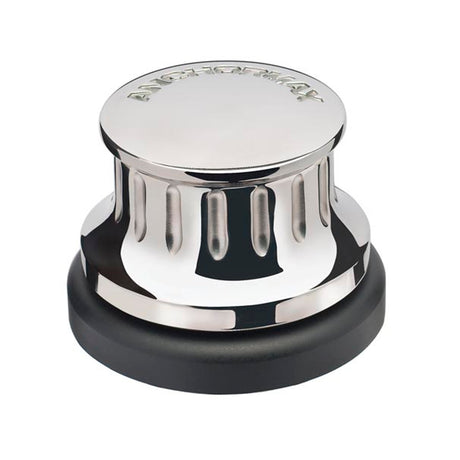




Maxwell Anchormax Vertical Capstan — Owner's Manual

Specifications, deck cut-out, wiring, operation and maintenance of the Maxwell Anchormax 500W vertical capstan, plus the service manual: model history (Anchormate, V1, V2), yearly service, motor service and the V1/V2 parts lists and kits.
Download PDF ▾

Specifications
| Item | Anchormax |
|---|---|
| Power supply (DC) | 12V/24V |
| Motor power | 500W |
| Working load | 386kg (850 lbs) |
| Haulage speed (dependant on the load) | 24m/min (76ft/min) |
| Net weight | 5.5kg (12lbs) |
| Circuit breaker/isolator | 12V: 80amp · 24V: 40amp |
| Cable length (battery → capstan → battery) | 12V | 24V |
|---|---|---|
| 0–10m (0–33') | 16 mm² / 6 AWG | 4 mm² / 12 AWG |
| 10–20m (33'–65') | 25 mm² / 4 AWG | 6 mm² / 10 AWG |
Cable sizes keep voltage drop at the motor under 10% under load, for copper conductors with 90° C insulation. Cables through an engine area may need to be larger; smaller cables reduce performance, larger ones can be used.
Location & Fitting
- Plan the location: the rode must feed correctly, the deck must be flat (fit a plinth if not), avoid bulkheads, wiring and piping below, and the mounting area must take the loads of capstan, anchor and rode.
- Use the cut-out template (part no. 7409, in the PDF downloads) to mark and cut the holes; align the load with the 'To Load' arrow. Print it at 100% and check the dimensions before cutting.
- Drill/cut the holes in order A to C with hole saws. Seal the edges with epoxy (not required for steel or aluminium).
- Seal the capstan to the deck with the gasket supplied. On aluminium or steel boats insulate the deckplate assembly from the deck to prevent electrolysis.
- Lower the deckplate into the cut-out and fasten with the nuts and washers supplied, tightening progressively and evenly. Firm, but do not over-tighten; no power tools.
Wiring
- Connection of power lines and control circuitry by qualified technicians, to local requirements (USCG, ABYC, NMMA, CE).
- A circuit breaker/isolator is required: no further than 1.8 m (6 ft) from the battery, accessible and dry. The circuit needs an isolator switch and either a fuse or circuit breaker.
- Footswitch approximately 500 mm (20") from the capstan, below-deck part in a dry place, arrow showing the direction of operation.
- When tightening the cables on the motor, hold the lower nut (A1) while tightening the upper nut (B1) to avoid damage inside the motor.
- Use crimp-on ring terminals with heat shrink, chafe protection through bulkheads; once tested, spray terminals with a dry corrosion-preventative film.
Hauling In
- Wind up to three turns of rope up the drum in the direction of pull.
- Keep a light tailing pull on the free end and start the capstan with the footswitch.
- As it rotates, increase the pull and tail hand over hand to haul the rope.
- Reduce the pull to slip the rope if required.
- Start the main engine before operating; keep fingers, clothing and hair clear and do not touch the footswitch while putting turns on.
- Extra turns increase grip and need less load on the tail. Maxwell recommends clockwise rotation.
- Turn the isolator off when the system is not in use.
Maintenance
| When | Task |
|---|---|
| After use | Wash down topworks with fresh water; check the rope for wear and wash it down. |
| Every 3 months | Clean the capstan; check all fasteners are tight; apply corrosion inhibitor to the under-deck components. |
| Every year | Motor serviced by a qualified technician; remove rust build-up from the casing and paint with a suitable coating. |
Service Manual Notes
Versions
- Anchormate: original design bought by Maxwell; no SP0064 csk screws between deckplate and baseplate, UHMWPE drum bearings (part 4229, still available to order), drum bore Ø42mm, V100 (SP0748) deck seal – replace with V110 (SP2768).
- Anchormax V1 (mid 1999 – January 2011): drum bore Ø44.2 with press-in plastic bearings, 3 csk screws added. 2001: aluminium cap and V110 seal (the V100 overstretched and cracked). January 2007: cap 4507 gets an o-ring groove; earlier caps were sealed with liquid gasket.
- Anchormax V2 (January 2011 on): all gears on bearings, stainless steel drum, 500W motor (SP4189) replacing the 600W (SP2142) with the same performance. Replacing the whole unit may be better than repairing a damaged one.
Servicing
- Never clamp the motor in a vice or knock it: the magnets dislodge.
- Gears are sold only as sets: P90014 (V1) and P90016 (V2), both excluding the ring gear. A damaged ring gear is removed by drilling or grinding through the ring.
- Reassemble deckplate and baseplate with liquid gasket; an anaerobic sealant is recommended (it will not form lumps that get into the gears).
- V1 / Anchormate: remove the top cap and slide off the drum; separate baseplate and deckplate by removing the 3 csk screws. The 600W motor SP2142 is replaced by SP4189 plus adaptor kit P104725.
- V2: remove the 3 csk screws, remove gear assembly 4226, pinion 7229 with bearing SP0683, then circlip SP3531 to free the drum (check the circlip has not stretched before reuse).
- Yearly: run the unit and note current and noise. At 12V, no more than 25Amp (V1) or 35Amp (V2). Inspect seals, bushes and bearings, clean carbon dust from the motor and regrease.
- Motor: brushes act axially, so the end cap springs apart when unbolted – keep the springs. Replace the motor if windings or insulation are burnt; standard brush length is 12.7mm.
Parts Lists

Anchormax V2
| Part no. | Description | |
|---|---|---|
| 7226 | Drum | Ask us to source it → |
| 4227 | Gear ring | Ask us to source it → |
| SP2794 | Oil seal 105×125×12mm | Ask us to source it → |
| 7427 | Bearing composite 32×47×20mm | Ask us to source it → |
| SP3526 | Circlip internal 35mm | Ask us to source it → |
| SP3920 | Deep groove bearing 15×35×11mm (6202) | Ask us to source it → |
| SP3531 | Circlip external 15mm | Ask us to source it → |
| 7224 | Deckplate top | Ask us to source it → |
| 7230 | Pinion secondary | Ask us to source it → |
| SP0682 | 5mm ball | Ask us to source it → |
| SP0684 | Bearing 6001 2RS 12×28×8mm | Ask us to source it → |
| 7227 | Spacer | Ask us to source it → |
| 4226 | Gear primary spur | Ask us to source it → |
| SP3524 | Circlip 10mm external | Ask us to source it → |
| SP0683 | Bearing 6000 2RS 10×26×8mm | Ask us to source it → |
| 7229 | Pinion primary | Ask us to source it → |
| 7225 | Deckplate bottom | Ask us to source it → |
| 7231 | Gasket | Ask us to source it → |
| SP0117 | CSK screw M6×16mm | Ask us to source it → |
| SP2792 | Oil seal 10×26×7mm | View part → |
| 3625 | Washer M8×24×2mm | Ask us to source it → |
| 7063 | Motor gasket Unipoint | Ask us to source it → |
| SP0467 | Spring washer M8 | Ask us to source it → |
| 4281 | Stud M8×97mm | Ask us to source it → |
| SP0366 | Nut M8 | Ask us to source it → |
| SP4189 | Motor | View part → |
| SP2931 | Motor gasket | Ask us to source it → |
| SP2932 | End cap & brush assembly | View part → |
Kits

| Part no. | Kit | |
|---|---|---|
| P90008 | Service kit Anchormax V1: V-ring seals V45A and V110A, 40mm upper and flanged bushes, bearings 6001LLU and 6000LLU | View part → |
| P102707 | Anchormax V1 drum kit: drum, 40mm upper and flanged bushes, internal gear ring | Ask us to source it → |
| P90014 | Gear set Anchormax V1 (excludes ring gear) | Ask us to source it → |
| P90016 | Gear kit Anchormax V2 (excludes ring gear): pinions 7229 and 7230, ball 5mm, bearing 12×28×8mm, spacer, circlip 10mm external | Ask us to source it → |
| P90017 | Bearing and seals kit Anchormax V2: oil seals 105×125×12mm and 10×26×7mm, composite bearing 32×47×20mm, bearings 15×35×11mm and 10×26×8mm, circlip external 15mm, motor gasket | View part → |
| P104725 | Adaptor kit to fit the 500W motor SP4189 in place of the original 600W SP2142 (V1 / Anchormate) | Ask us to source it → |

Anchormax V1
| Part no. | Description | |
|---|---|---|
| SP0064 | M8×16 CSK screw | Ask us to source it → |
| SP0720 | O-ring 20×2mm | View part → |
| 4507 | Retaining cap | Ask us to source it → |
| 4683 | Drum (kit P102707) | Ask us to source it → |
| 4679 | 40mm bush – upper (kits P102707, P90008) | Ask us to source it → |
| 4682 | 40mm flanged bush (kits P102707, P90008) | Ask us to source it → |
| 4227 | Internal gear ring (kit P102707) | Ask us to source it → |
| SP2760 | V-ring seal V45A (kit P90008) | Ask us to source it → |
| SP2768 | V-ring seal V110A (kit P90008) | Ask us to source it → |
| SP0684 | Ball bearing 6001LLU (kits P90008, P90014) | Ask us to source it → |
| SP0683 | Ball bearing 6000LLU (kit P90008) | Ask us to source it → |
| 4225 | Secondary reduction pinion (kit P90014) | Ask us to source it → |
| SP0682 | 5mm stainless steel ball (kit P90014) | Ask us to source it → |
| 4224 | Primary reduction pinion (kit P90014) | Ask us to source it → |
| 4226 | Primary spur gear (kit P90014) | Ask us to source it → |
| 4222 | Deckplate | Ask us to source it → |
| 4223 | Bottom baseplate | Ask us to source it → |
| SP0117 | M6×12 raised CSK screw | Ask us to source it → |
| 4281 | M8 stud | Ask us to source it → |
| 3625 | M8×24 retaining washer | Ask us to source it → |
| SP0366 | M8 stainless steel hex hd nut | Ask us to source it → |
| SP2931 | Motor gaskets | Ask us to source it → |
| SP2932 | Brush end cap assembly | View part → |
| SP2142 | Motor (discontinued: use SP4189 combined with P104725) | Ask us to source it → |
| SP0482 | Fibre washers | Ask us to source it → |
The service manual also holds the Anchormate parts drawing and the V2 section view: see the PDF downloads.
Need a part that isn't listed? Ask us to source it and quote the part number from the PDF.
Products in this Manual
-

-
-
-
-

Maxwell Motor 12V PM UNIPOINT DM-723M
MAXSP4189
$373.00 USDList Price: $441.01 USDUnit price /Unavailable -
-
-
Maxwell Windlass - Anchormax 500W Vertical Electric 12V Drum Only
MAXANCHORMAX
$1,229.91 USDList Price: $1,537.39 USDUnit price /Unavailable