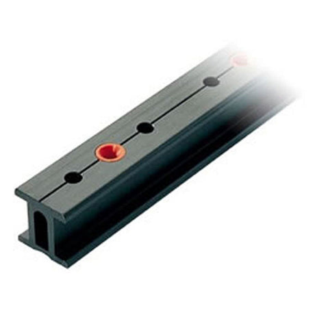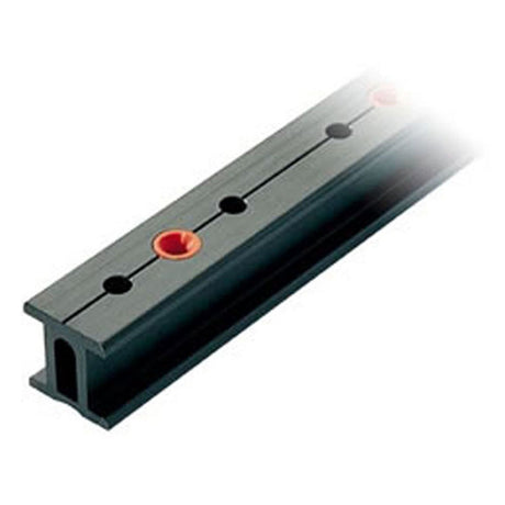




Ronstan Series 32 I-Track Safety Rail System — Product Manual

Design, installation, load testing and inspection of the Ronstan Series 32 I-Track safety rail for pilot launches and commercial vessels: fastening rules, span limits, how far the track can be sprung, and the track parts list.

Compliance & System
- Meets the Australian National Standard for Commercial Vessels (NSCV), Edition 2.0, Part C, Section 1, 6.19.4.d (Pilot Launches – Equipment).
- Tethers crew to the vessel during pilot transfer or similar operations, with personal protection equipment. Not for lifting, mooring or any other purpose.
- Load requirements met: 3.0kN static load with no permanent deformation; 6.0kN static load without breaking. NSCV recommends harnesses, tethers and lanyards to ISO12401, AS2227 or equivalent.
- One user per car. Maximum 2 cars/users on the system at any time, and never more than one car locked in a single span of rail between mounting brackets.
- Marine grade stainless steel car with lanyard attachment point, running on a continuous rail of S32 I-Track sections mounted to handrails, superstructure or support brackets. RC63221 plunger stop cars can be fixed "on-station" during pilot transfer or locked disengaged to run freely.
Installation Requirements
- Install only by competent persons or organisations. The rail mounts on a vertical (0°) or horizontal (90°) surface; cars must travel in a horizontal plane within ±5° (exceptions where needed for deck slope or camber).
- Track fastenings: M6 or 1/4" 316 stainless countersunk fasteners, minimum tensile strength 700MPa (101ksi), A4-70 DIN7991, torque no more than 7.1Nm (5.2ft lbf).
- Mounting brackets are specified and installed by the designer / builder; brackets, substrate and backing plates must support a minimum 600kg (1320lb) ultimate static load.
- Unsupported spans up to 900mm (35 7/16"). Each span or join needs at least two fasteners at each end at a maximum of 100mm (3 15/16") centres, with a joiner and a bracket or splice plate. Across a join of standard rails the fastener spacing is 96mm.
- Standard lengths can be shortened on site. RC6320R500A (90°, 500mm radius A-bend) can be shortened to suit broader angles.
- RC63286 end stops (rubber buffer) take a minimum of 2 fastenings; through-bolts recommended.
- Isolate dissimilar metals: the rail includes RC7320-INS nylon insulator bushes; use isolating compound on all fastenings and joins, and plastic isolating pads between stainless brackets and aluminium track.
- Fit cars with the lanyard attachment points facing downward or outboard (the fall load path), check they run freely, then fit the end stops.
| Track length | Max. horizontal deflection when sprung | Max. vertical deflection when sprung |
|---|---|---|
| 1m | 50mm | 25mm |
| 1.5m | 90mm | 45mm |
| 2.0m | 150mm | 75mm |
| 3.0m | 300mm | 150mm |
Straight track may be "sprung" on site into shallow bends without permanent bending, within these limits.
Track Parts
| Part No. | Description | |
|---|---|---|
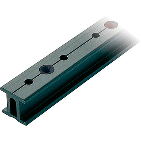
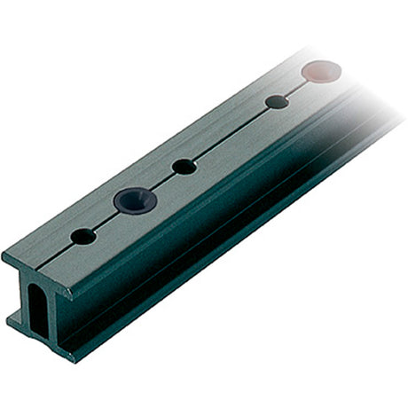
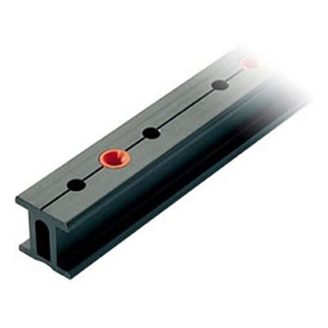
| RC6320-1.0 | Track, 996mm (39 3/16"), black | View part → |
| RC6320-1.5 | Track, 1496mm (58 7/8"), black | View part → |
| RC6320-3.0 | Track, 2996mm (117 15/16"), black | View part → |
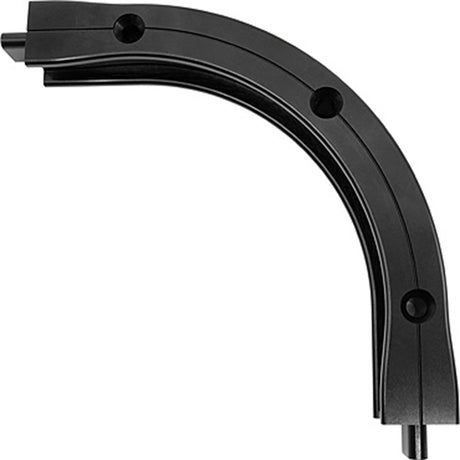
| RC6320R125A | Track, 293mm (11 9/16"), black, 90° × 125mm radius, horizontal A-bend | View part → |
| RC6320R500A | Track, 1196mm (47 1/16"), black, 90° × 500mm radius, horizontal A-bend | View part → |
| RC6320R515A | Track, 1996mm (78 9/16"), black, 15° deflection, horizontal A-bend | View part → |
| RC63286 | End stop, rubber buffer | View part → |
| RC6320P | Track splice plate, stainless steel | Ask us to source it → |
| RC6320J | Track joiner | Ask us to source it → |
| RC63221 | Plunger stop car | Ask us to source it → |
| RC7320-INS | Nylon insulator bush | Ask us to source it → |
Standard bends are A-bend configuration with the track on a horizontal surface (90°). Custom lengths, configurations and radius bends are quoted by Ronstan on request; the manual shows a typical design layout.
Load Testing & Documentation
- After installation and before first use, and then at intervals of not more than 5 years or after a fall or incident: apply 3.0kN (300kg) to a single car for at least 30 seconds at each extremity and near the midpoint, oriented to simulate the fall load path, then check for permanent deformation.
- Record results with photographs in the installation documentation (Appendix A) or 5-yearly inspection record (Appendix D). Keep the documentation with the user, on site.
- Use only by trained, competent persons with approved personal protective equipment, and with a rescue plan in place.
Inspection & Maintenance
Before each use
- Rail securely fixed to its brackets / surface, both end stops in place.
- Cars run smoothly and freely along the track; plunger operating correctly.
- No excessive wear, corrosion, deformation or breakage.
Annual and 5-yearly
- Annual inspection by a competent person (Appendix C): fastenings, wear and damage, plunger function, light grease on the plunger assembly, corrosion, fresh-water cleaning, free-running wheels.
- 5-yearly (Appendix D): remove an end stop and all cars; check wheels and bearings rotate smoothly and replace cars with worn bearings or wheels. As a minimum, replace all cars at the second 5-yearly inspection (10 years cumulative service).
- Damaged parts or any doubt: remove from service until repaired and approved by a competent person (Appendix B). After any fall, do not use until inspected and confirmed safe.
Maintenance
- Rinse regularly with fresh water; a mild soapy solution may be used, then rinse thoroughly.
- No spray lubricants on the rail and wheels.
- Keep an equipment record for each component (Appendix B).
Need a part that isn't listed? Ask us to source it and quote the part number from the PDF.
Products in this Manual
-

-

RONRC6320R515A
$203.00 USDList Price: $241.05 USDUnit price /Unavailable -
Ronstan Track Series 32 I-Beam Track 'A' Bend (Black) - Aluminum alloy - Length: 3.9 ft (1195.4 mm)
RONRC6320R500A
$192.00 USDList Price: $227.34 USDUnit price /Unavailable -
Ronstan Track Series 32 I-Beam Track 'A' Bend (Black) - Aluminum alloy - Length: 0.9 ft (293.0 mm)
RONRC6320R125A
$511.00 USDList Price: $628.26 USDUnit price /Unavailable -
Ronstan Track Series 32 I-Beam (Black) - Aluminum alloy - Length: 9.8 ft (2996.0 mm)
RONRC632030
$365.00 USDList Price: $432.28 USDUnit price /Unavailable -
Ronstan Track Series 32 I-Beam (Black) - Aluminum alloy - Length: 4.9 ft (1496.0 mm)
RONRC632015
$185.00 USDList Price: $219.26 USDUnit price /Unavailable -
Ronstan Track Series 32 I-Beam (Black) - Aluminum alloy - Length: 3.3 ft (996.0 mm)
RONRC632010
$144.00 USDUnit price /Unavailable