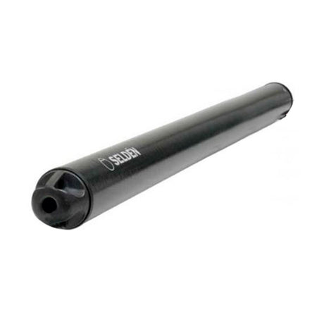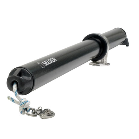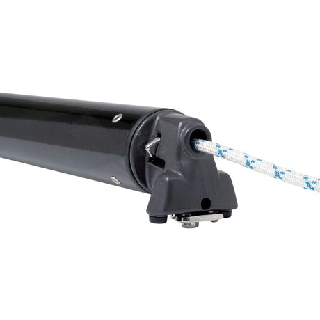




Selden Carbon Gennaker Pole Kit — Instructions

INSTRUCTIONS
Cutting, drilling and assembling a Selden carbon deck-fitted gennaker pole (GC076 to GC121), with the PS 742 section length and rivet position tables.
DocumentSelden Carbon Gennaker Pole Kit Instructions
FormatPDF · 2 pages · 0.1 MB
LanguageEnglish

Safety
- Cured carbon fibre gives sharp slivers: long sleeves and heavy duty gloves; barrier cream against carbon dust.
- Safety goggles and a face mask when cutting, sanding or drilling; latex gloves when handling mixed adhesive.
- A vacuum cleaner is highly recommended for frequent removal of dust.
- All metal surfaces (including fastenings) that contact carbon fibre must be insulated.
Drilling Carbon
- Standard HSS bits damage the laminate: use "Dagger" drill bits, abrasive jigsaw and hole-saw blades, and a diamond-edged hacksaw blade (Selden item 592-102).
- "Dagger" bit Ø 6.4 mm: 1500 rpm (item 592-081).
- Mask the hole area, support the drill's weight, apply no pressure, and give extra support just before breaking through.
Tube Preparation and Assembly
- Get the finished DBS (distance between supports, aft of the bow ring forward edge) and USL (unsupported length, forward of the bow ring) from PS 742.
- Mark the cut with a grease pencil or white correction fluid; ends must be precisely square.
- Cut with the special blade, cutting only towards the inside of the tube, rotating it often; smooth the edges with grit cloth.
- Drill the rivet holes for the inboard end, rivet it in place and remove the loose mandrel heads.
- Run a messenger line through the inboard end to the open end.
- Bond the outboard end with the supplied 2-part Plexus adhesive (working time before curing 15 minutes), aligned as in the diagram.
Section Length Dimensions (mm)
| Section | C | E | F | G | H | J | D | XL | POA |
|---|---|---|---|---|---|---|---|---|---|
| GC076 | 35 | 20 | 46 | 100 | 70 | 42 | DBS – 116 | (DBS+USL) – 88 | (DBS+USL) +20 |
| GC088 / GC089 | 35 | 20 | 66 | 100 | 70 | 62 | DBS – 136 | (DBS+USL) –128 | (DBS+USL) +20 |
| GC100 / GC101 | 40 | 31 | 14 | 150 | 95 | 31 | DBS – 109 | (DBS+USL) – 45 | (DBS+USL) +31 |
| GC120 / GC121 | 40 | 31 | 34 | 150 | 95 | 51 | DBS – 129 | (DBS+USL) – 85 | (DBS+USL) +31 |
| Inboard end rivet positions | X | Y |
|---|---|---|
| GC076 | 30 | 85 |
| GC088 / GC089 | 35 | 100 |
| GC100 / GC101 | 30 | 130 |
| GC120 / GC121 (screw fix) | 40 | 150 |
Inboard end: 4 x ø6.5 ±0.1 holes. The outboard end is bonded, not riveted.
Need a part that isn't listed? Ask us to source it and quote the part number from the PDF.
Products in this Manual
-


Selden Gennaker Bowsprit Kit - 121 mm. Dia. (Carbon Fiber)
SEL12112190
$6,100.00 USDList Price: $7,570.80 USDUnit price /Unavailable -
Selden Gennaker Bowsprit Kit - 120 mm. Dia. (Carbon Fiber)
SEL12012090
$6,100.00 USDList Price: $7,570.80 USDUnit price /Unavailable -

SELDEN-GENN-POLE-GC076-KIT-POL-3000
$2,180.00 USDUnit price /Unavailable