



Selden Furlex 200S & 300S — Owner's Manual

Assembly and operating manual plus the full spare parts list for the Selden Furlex 200S and 300S jib furlers: dimensions, toggles, forestay and foil calculations, halyard routing, maintenance and every part number.
Download PDF ▾

This manual is split into 3 pages: Part 1 · Part 2 → · Part 3 →
Key Dimensions
Discontinued model – documents and spare parts as printed.
Lower bearing assembly (mm)
| Furlex | DD | DH | DW |
|---|---|---|---|
| 200 S | Ø 186 (7 1/3") | 120 (4 3/4") | 95 (3 3/4") |
| 300 S | Ø 216 (8 1/2") | 150 (5 7/8") | 115 (4 1/2") |
Top eye terminal
| Furlex | Wire | TED | TET |
|---|---|---|---|
| 200 S | Ø6 (1/4") | 12,2 (1/2") | 6 (1/4") |
| 200 S | Ø7 (9/32") | 13,5 (9/16") | 7 (9/32") |
| 200 S | Ø8 (5/16") | 16,5 (5/8") | 10 (3/8") |
| 300 S | Ø8 (5/16") | 16,5 (5/8") | 10 (3/8") |
| 300 S | Ø10 (3/8") | 16,5 (5/8") | 10 (3/8") |
Sail measurements
| 200 S | 300 S | |
|---|---|---|
| Head deduction F | 540 (21 1/2") | Ø8: 550 (22"); Ø10: 650 (25 5/8") |
| Tack deduction E (add any extra toggle or link) | 330 (13") | 400 (15 3/4") |
| Cutback CB | 60 (2 3/8") | 80 (3 1/8") |
| Luff groove internal diameter DLG | Ø6 (1/4") | Ø7.5 (9/32") |
| Luff groove width WLG | 3.0 (1/8") | 3.0 (1/8") |
| Extrusion overall | 31x21 (1 7/32" x 13/16") | 39x27 (1 17/32" x 1 1/16") |
Max. luff length = FL – (F + E). The model designation is on the line drum top. Torx sockets: M5 T25, M6 T30, M8 T40 (bits included).
Forestay Attachment & Toggles
- The forestay must articulate in all directions; in most cases fit a toggle between the Furlex stay and the fittings (masthead rigs: always).
- Selden fractional fittings: 505-018 (Ø6 & 7 mm wire) connect with an eye/fork toggle; 505-020 (Ø8 & 10 mm) to the existing toggle; O-35 (517-905) and O-50 (517-911) connect directly. T-terminal: fit a T/fork toggle.
- Raising the drum for anchor work: use an extension link, always with a toggle between link and stemhead fitting.
- Below-deck installation: first turning point at least 300 mm (12") from the drum, tack as close to deck level as possible, system clear of the well sides, well properly drained.
| Part No. | Toggle | Forestay | Length H | Details | |
|---|---|---|---|---|---|
| 174-104 | Eye/fork toggle | Ø6 (1/4") | 40 (1 1/2") | Eye D1 11, clevis pin D2 11, fork W2 12 | Ask us to source it → |
| 174-105 | Eye/fork toggle | Ø7 (9/32") | 45 (1 3/4") | Eye D1 13, clevis pin D2 13, fork W2 12 | Ask us to source it → |
| 174-106 | Eye/fork toggle | Ø8 (5/16") | 50 (2") | Eye D1 16, clevis pin D2 15.8, fork W2 12 | Ask us to source it → |
| 174-107 | Eye/fork toggle | Ø10 (3/8") | 65 (2 1/2") | Eye D1 16, clevis pin D2 15.8, fork W2 20 | Ask us to source it → |
| 517-046-02 | Fork/fork toggle | Ø6 | 40 (1 1/2") | D1 12, W1 11, D2 10, W2 11 | View part → |
| 517-047-02 | Fork/fork toggle | Ø7 | 40 (1 1/2") | D1 12, W1 11, D2 12, W2 12,5 | View part → |
| 517-048-02 | Fork/fork toggle | Ø8 | 50 (2") | D1 14, W1 14, D2 14, W2 15,5 | View part → |
| 517-060-04 | Fork/fork toggle | Ø10 | 55 (2 3/16") | D1 16, W1 14, D2 16, W2 16 | View part → |
| 174-122 | T/fork toggle | Ø6 | 80 (3 1/4") | D2 11, W2 12 | Ask us to source it → |
| 174-123 | T/fork toggle | Ø7 | 90 (3 1/2") | D2 13, W2 14 | Ask us to source it → |
| 174-124 | T/fork toggle | Ø8 | 100 (4") | D2 15.8, W2 16 | Ask us to source it → |
| 517-066-01 | Stemball/eye toggle with fork/fork toggle | Ø6 | 152 (6") | Stemball D1 26, D2 10, W2 11 | View part → |
| 517-067-01 | Stemball/eye toggle with fork/fork toggle | Ø7 | 157 (6 1/4") | Stemball D1 34, D2 12, W2 12,5 | Ask us to source it → |
| 517-097-01 | Stemball/eye toggle with fork/fork toggle | Ø7 | 153 (6") | Stemball D1 26, D2 12, W2 12,5 | View part → |
| 517-068-01 | Stemball/eye toggle with fork/fork toggle | Ø8 | 197 (7 3/4") | Stemball D1 34, D2 16, W2 15,5 | View part → |
| 517-068-02 | Stemball/eye toggle with fork/fork toggle | Ø10 | 202 (8") | Stemball D1 34, D2 16, W2 16 | View part → |
| 517-063-01 | Eye/fork extension link | Ø6 / Ø7 | 90 (3 9/16") | D1 12, W1 11, eye D2 12, gauge W2 6 | View part → |
| 517-062-01 | Eye/fork extension link | Ø8 / Ø10 | 130 (5") | D1 16, W1 14, eye D2 16,5, gauge W2 10 | View part → |
Forestay Wire & Luff Extrusion Length
WL = FL – T, where FL is the existing forestay length including rigging screw (deduct the length H of any links or extra toggles). Deductions:
| Furlex / wire | T without rigging screw | T with rigging screw | A+B without rigging screw | A+B with rigging screw | Distance tube deduction (without / with RS) |
|---|---|---|---|---|---|
| 200 S Ø6 | 110 mm (4 5/16") | 200 mm (7 7/8") | 1310 mm (51 1/2") | 1230 mm (48 7/16") | 345 / 365 mm |
| 200 S Ø7 | 110 mm (4 5/16") | 200 mm (7 7/8") | 1310 mm (51 1/2") | 1230 mm (48 7/16") | 345 / 365 mm |
| 200 S Ø8 | 110 mm (4 5/16") | 195 mm (7 3/4") | 1310 mm (51 1/2") | 1230 mm (48 7/16") | 355 / 380 mm |
| 300 S Ø8 | 130 mm (5 1/8") | 230 mm (9") | 1380 mm (54 5/16") | 1280 mm (50 3/8") | 335 / 375 mm |
| 300 S Ø10 | 130 mm (5 1/8") | 235 mm (9 1/4") | 1380 mm (54 5/16") | 1280 mm (50 3/8") | 345 / 385 mm |
- Foil: one 1000 mm (39 3/8") bottom extrusion with long joining sleeve, 2400 mm (94 1/2") full-length extrusions and one 2000 mm (78 3/4") top extrusion.
- C+D = WL – (A+B); C = largest number of 2400 mm extrusions shorter than C+D; top extrusion D = (C+D) – C; top distance tube E = D – deduction. Example (200 S Ø8 with rigging screw): FL 13.000 – 195 = WL 12.805; 12.805 – 1.230 = 11.575; 4 extrusions = 9.600; D = 1.975; E = 1.595.
- If the top extrusion is shorter than 400 mm (15 3/4"), swap the uppermost 2400 mm extrusion for the 2000 mm one: deduct 400 mm from C and add 400 mm to D.
- Check before cutting the wire: cutting mark to bottom of the 1000 mm extrusion approx. 200 mm (7 7/8") for 200 S Ø6/7/8 and 240 mm (9 7/16") for 300 S without rigging screw; with rigging screw approx. 140 mm (Ø6, Ø7), 145 mm (200 S Ø8) and 180 mm (7 1/8") for 300 S.
- Sta-Lok: wire core protrudes approx. 2 mm (3/32") from the wedge; no strand in the wedge slot; locking adhesive on the thread.
- Alignment mark on the 1000 mm extrusion: 200 S 31 mm (1 7/32"), 300 S 41.5 mm (1 5/8").
Halyard Routing
- Halyard-to-forestay angle 5–10°; less can cause halyard wrap, which may damage the forestay and put the rig at risk. More than 10° wears the halyard lead.
- Two bronze halyard leads are supplied (200 S: 508-159, 2 screws each; 300 S: 508-128, 3 screws each) with self-adhesive insulator sheets. Drill Ø5.3 mm (7/32") and fit with greased self-tapping M6 screws.
- Lead position on Selden masts: masthead 220 mm (8 5/8") for 200 S, 270 mm (10 5/8") for 300 S; triple combi (fractional) 100 mm (4") / 125 mm (5").
- Keep at least 50 mm (2") between the halyard swivel and the top guard; set luff length with a pendant spliced to the head if needed.
- Lead a spinnaker halyard round the upper shroud and aft of the spreaders, never parallel to the Furlex.
| Part No. | Sheave box | Wire halyard | Rope halyard | Sheave width | |
|---|---|---|---|---|---|
| 505-004-10 | AL-45 | Ø4 (5/32") | Ø8 (5/16") | 13 mm (1/2") | Ask us to source it → |
| 505-006-10 | AL-70 | Ø5 (3/16") | Ø10 (3/8") | 13 mm (1/2") | Ask us to source it → |
| 505-012-10 | AL-90 | Ø6 (1/4") | Ø12 (1/2") | 16 mm (5/8") | Ask us to source it → |
Furling Line
- Wind approx. 30 turns onto the drum by turning the foil. UV strip to starboard → turn the foil clockwise, line exits to port.
- 3–5 turns must remain on the drum with the largest sail tightly furled.
- Cockpit turning block (not supplied): working load at least 3000 N (675 lb) for 200 S, 5000 N (1125 lb) for 300 S; swivel block plus a normal cleat.
- 200 S: four stanchion blocks 538-971-02 for Ø25 mm (1") stanchions. 300 S: one articulated block (Ø25 pulpit) and four fixed blocks for Ø25 mm; on Ø30 mm (1 1/4") stanchions use M6-25 mm screws.
- Line lock kit (595-162-E): 539-256-02 (200 S), 539-256-03 (300 S); place line and lock in the drum half and tighten hard with a T25 Torx key.
- Racing: remove line guide and drum, lower the swivel below the sail feeder. Min. distance forestay attachment to tack: 200 S 100 mm (4"), 300 S 125 mm (5").
Adjusting the Forestay Length
- With rigging screw: free the luff screws (mark the extrusion first), remove split and clevis pin, slide the lower bearing assembly up and turn only the rigging screw body. Re-align the flat faces so the bearing assembly locks the screw. Never exceed the adjustment below or force the end stop.
- Without rigging screw: lengthen with extra toggles. On a Ø8 mm (5/16") forestay of 15400 mm (50'6"), a 50 mm (2") toggle moves the masthead 158 mm (6 5/8") aft. Never shorten by removing the lower Furlex toggle.
- Re-making the terminal shortens the stay about 5 mm (3/16"): masthead moves 16 mm (5/8") forward on a 15 400 mm forestay. Permanent tension must not exceed 20% of the wire's breaking load.
| Part No. | Furlex | Forestay | Adjustment | |
|---|---|---|---|---|
| 174-536-11 | 200 S | Ø6 (1/4") | 60 (2 3/8") | Ask us to source it → |
| 174-537-11 | 200 S | Ø7 (9/32") | 60 (2 3/8") | Ask us to source it → |
| 174-538-11 | 200 S | Ø8 (5/16") | 60 (2 3/8") | Ask us to source it → |
| 174-519-11 | 300 S | Ø8 (5/16") | 80 (3 1/8") | Ask us to source it → |
| 174-520-11 | 300 S | Ø10 (3/8") | 80 (3 1/8") | Ask us to source it → |
Maintenance & Rigging
- Lubricate once a year (or at each unrigging) with the Furlex grease: hole A in the adapter (slide the adapter up), B on the front of the tack ring, C between terminal part and line drum, D the tack ring's lower bearing (every other cycle, drum removed). Halyard swivel: recess E (upper bearing) and opening F (lower bearing).
- Halyard leads: inspect yearly, file sharp edges, replace at 50% wear (not covered by the 2-year warranty).
- Wash with fresh water and mild detergent, rinse well; silicone-free polish or wax on the extrusions. Store with the mast, never wrapped damp in plastic; in frost areas store dry or with the centre sections raised.
- Rigging: tension the forestay to 20% of the wire's breaking load (masthead: approx. 15% of backstay breaking load; forestay ≈ 1.25 × backstay tension). Split pins opened ~20°.
- Do not dismantle the halyard swivel or lower bearing assembly (loose balls). A locked terminal thread releases at approx. 100°C (212°F). Seized foil joints: drill out the connector bosses with Ø6 mm (200 S) or Ø8 mm (300 S).
Troubleshooting
| Problem | Probable cause | Action |
|---|---|---|
| Sail will not unfurl, or only partly | Halyard wrapped round the foil; furling line tangled; forestay too slack; dirt/salt in bearings; too much halyard tension | Ease halyard and reverse; free the line; tension backstay or shorten the Furlex; rinse and grease; ease halyard |
| Sail hard to furl | No line on drum; excessive wind pressure; windward sheet not released; free turn not working; large turning angles | Wind more line; ease leeward sheet; release sheet; re-route the line |
| System wobbles | Forestay too loose; halyard swivel upside down; line guide chafing drum | Tension forestay/backstay; fit swivel correctly; adjust the fitting |
| Sail hard to hoist | Luff tape too thick; dirt in groove; halyard routing | See sail measurements; clean groove; check sheaves |
| Luff cannot be tensioned | Swivel touches top guard; halyard angle too great | Shorten the sail or move the halyard lead up |
| UV strip inside the roll | Line wound wrong way on drum | Empty the drum and rewind the right way |
| Leech flogs / closes | Sheeting point wrong; leech line | Move sheeting point forward / aft; consult sailmaker |
Halyard Swivel & Lower Swivel Parts
Halyard swivel (A)
| Part No. | Item | Description | Dimension | Fits | |
|---|---|---|---|---|---|
| 539-581-01 | A | Halyard swivel assembly | 200 S | View part → | |
| 539-281-01 | A | Halyard swivel assembly | 300 S | View part → | |
| 539-582 | A1 | Sliding sleeve | Ø74x162 | 200 S | View part → |
| 539-282 | A1 | Sliding sleeve | Ø90x173 | 300 S | View part → |
| 158-005 | A2 | Locking nut | M6 | 200 S, 300 S | Ask us to source it → |
| 539-581 | A3 | Hub | Ø52x120 | 200 S | Ask us to source it → |
| 539-281 | A3 | Hub | Ø62x130 | 300 S | View part → |
| 162-030 | A4 | Screw | MFT 6x12 | 200 S, 300 S | Ask us to source it → |
| 539-272 | A5 | Ball bearing ring, outer | Ø68/52-16 | 200 S | View part → |
| 539-270 | A5 | Ball bearing ring, outer | Ø83/64-16 | 300 S | View part → |
| 539-034 | A6 | Ball | Ø6 | 200 S | Ask us to source it → |
| 539-128 | A6 | Ball | Ø8 | 300 S | Ask us to source it → |
| 539-583 | A7 | Eye ring (only as assembly A7–A8) | 77x105 | 200 S | Ask us to source it → |
| 539-283 | A7 | Eye ring (only as assembly A7–A8) | 91x118 | 300 S | Ask us to source it → |
| 539-583-01 | A7–A8 | Eye ring with label, assembly | 200 S | View part → | |
| 539-283-01 | A7–A8 | Eye ring with label, assembly | 300 S | View part → | |
| 591-398 | A8 | Label | 18x213 | 200 S | Ask us to source it → |
| 591-397 | A8 | Label | 24x251 | 300 S | Ask us to source it → |
| 319-656 | A9 | Buffer | Ø5x8 | 200 S, 300 S | Ask us to source it → |
| 164-441 | A10 | Washer | Ø62/52-3 | 200 S | View part → |
| 164-440 | A10 | Washer | Ø74/62-3 | 300 S | View part → |
| 301-508 | A11 | Clip ring | MST 204 | 200 S | Ask us to source it → |
| 301-507 | A11 | Clip ring | MST 243 | 300 S | Ask us to source it → |
| 539-578 | A12 | Cover | Ø77x5 | 200 S | Ask us to source it → |
| 539-278 | A12 | Cover | Ø88x8 | 300 S | Ask us to source it → |
| 307-025 | A13 | Twisted shackle | 42 mm | 200 S, 300 S | View part → |

Lower swivel (B)
| Part No. | Item | Description | Dimension | Fits | |
|---|---|---|---|---|---|
| 539-551-01 | B | Lower swivel assembly | 200 S | View part → | |
| 539-251-02 | B | Lower swivel assembly | 300 S | View part → | |
| 539-554 | B1 | Adapter | Ø78x40 | 200 S | View part → |
| 539-254 | B1 | Adapter | Ø90x44 | 300 S | View part → |
| 155-823 | B2 | Screw (machined) | MRT 6x19 | 200 S | Ask us to source it → |
| 155-822 | B2 | Screw (machined) | MRT 8x20 | 300 S | Ask us to source it → |
| 539-553 | B3 | Carrier (only as assembly B3–B5) | Ø73x44 | 200 S | Ask us to source it → |
| 539-253 | B3 | Carrier (only as assembly B3–B5) | Ø90x50 | 300 S | Ask us to source it → |
| 539-552-01 | B3–B5 | Carrier and hub, assembly | 200 S | View part → | |
| 539-252-01 | B3–B5 | Carrier and hub, assembly | 300 S | Ask us to source it → | |
| 162-064 | B4 | Screw | MFT 5x10 | 200 S | Ask us to source it → |
| 162-030 | B4 | Screw | MFT 6x12 | 300 S | Ask us to source it → |
| 539-552 | B5 | Hub (only as assembly B3–B5) | Ø52x147 | 200 S | Ask us to source it → |
| 539-252 | B5 | Hub (only as assembly B3–B5) | Ø62x186 | 300 S | Ask us to source it → |
| 539-272 | B6, B16 | Ball bearing ring, outer | Ø68/52-16 | 200 S, 300 S | View part → |
| 539-270 | B6 | Ball bearing ring, outer | Ø83/64-16 | 300 S | View part → |
| 539-034 | B7, B15, B17 | Ball | Ø6 | 200 S, 300 S | Ask us to source it → |
| 539-128 | B7, B15 | Ball | Ø8 | 300 S | Ask us to source it → |
| 539-556 | B8 | Tack ring | Ø105x40 | 200 S | Ask us to source it → |
| 539-297 | B8 | Tack ring | Ø120x61 | 300 S | Ask us to source it → |
| 307-021 | B9 | D-shackle | 32 mm | 200 S, 300 S | View part → |
| 319-656 | B11 | Buffer | Ø5x8 | 200 S, 300 S | Ask us to source it → |
| 164-441 | B12, B18 | Washer | Ø62/52-37 (as printed) / Ø62/52-3 | 200 S, 300 S | View part → |
| 164-440 | B12 | Washer | Ø74/62-3 | 300 S | View part → |
| 301-508 | B13, B19 | Clip ring | MST 204 | 200 S, 300 S | Ask us to source it → |
| 301-507 | B13 | Clip ring | MST 243 | 300 S | Ask us to source it → |
| 539-551 | B14 | Shaft | Ø58/42-194 | 200 S | Ask us to source it → |
| 539-251 | B14 | Shaft | Ø62/52-250 | 300 S | Ask us to source it → |
| 539-521 | B16 | Ball bearing ring, outer | Ø57/50-15 | 200 S | Ask us to source it → |
| 164-443 | B18 | Washer | Ø52/42-3 | 200 S | View part → |
| 301-510 | B19 | Clip ring | MST 173 | 200 S | Ask us to source it → |
| 165-108 | B20 | Clevis pin | Ø8x50 | 200 S | View part → |
| 165-213 | B20 | Clevis pin | Ø10x58 | 300 S | View part → |
| 301-047 | B21 | Split pin | 2,3x12 | 200 S | View part → |
| 301-048 | B21 | Split pin | 2,3x16 | 300 S | View part → |

Do not dismantle the halyard swivel or lower bearing assembly: the balls are loose and difficult to refit.
Need a part that isn't listed? Ask us to source it and quote the part number from the PDF.
Products in this Manual
-


Selden Drum Line Guide Fitting Assembly for 200S Furlers
SEL-SPR-539-560-01
$86.95 USDUnit price /Unavailable -

-
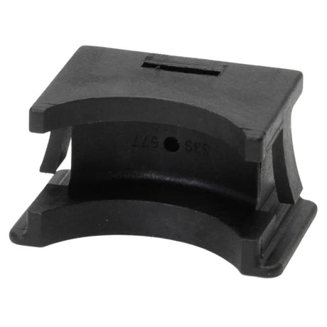
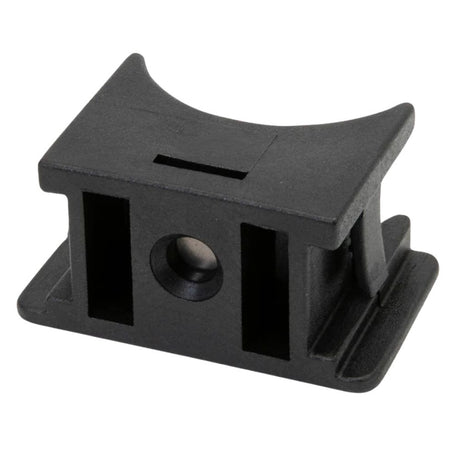
Selden Drum Lockblock & Disc Assembly for 200S Furlers
SEL-SPR-539-577-01
$30.99 USDUnit price /Unavailable -
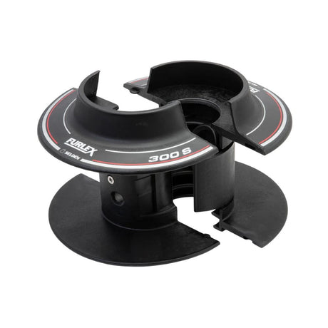
Selden Drum Line Half (Pair) for 200S Furlers
SEL-SPR-539-557-04
$174.00 USDUnit price /Unavailable -
Selden Lubricating Grease (90 g) - for Furlex, Winches and Furling Masts
SELDEN-LUBRICATING-GREASE-TUBE-90-G
$20.99 USDUnit price /Unavailable -
-
Selden Drum Line Guide Fitting Assembly for 300S Furlers
SEL-SPR-539-260-01
$107.95 USDUnit price /Unavailable -
Selden Drum Lockblock & Disc Assembly for 300S Furlers
SEL-SPR-539-277-01
$39.99 USDUnit price /Unavailable -
Selden Head Swivel Top Guard for 300S Furlers
SEL-SPR-539-286-01
$30.99 USDUnit price /Unavailable -
Selden Forestay Wire Pack (15.4m - 7mm) for 200S Furlers
SEL-SPR-601-005-62
$325.00 USDList Price: $379.00 USDUnit price /Unavailable -
Selden Intermediate Extrusion Assembly (2.4 m) for 200S Furlers
SEL-SPR-539-565-06
$255.00 USDUnit price /Unavailable -

Selden Connecting Plate 58x11 mm for Furlex 200S/TD/E Foil System
SELDEN-CONNECT-PLATE-58X11F200AL
$16.99 USDUnit price /Unavailable -
Selden Intermediate Extrusion Assembly (2.0 m) for 200S Furlers
SEL-SPR-539-564-01
$184.00 USDUnit price /Unavailable -
Selden Stainless Drum Cover for Furlex 200S
SELDEN-COVER-ASSY-FLX-200S
$130.00 USDUnit price /Unavailable -
Selden LINE GUARD BKT ASSY F200S
SELDEN-LINE-GUARD-BKT-ASSY-F200S
$49.99 USDUnit price /Unavailable -
Selden Drum Line Half (Pair) for 300S Furlers
SEL-SPR-539-250-03
$169.00 USDUnit price /Unavailable -
Selden Tack Swivel Wedge (36mm - 7mm) for 200S Furlers
SEL-SPR-301-153
$32.99 USDUnit price /Unavailable -
Selden Tack Swivel Wedge (33mm - 6mm) for 200S Furlers
SEL-SPR-301-152
$28.99 USDUnit price /Unavailable -
Selden Tack Swivel Socket (7mm) for 200S Furlers
SEL-SPR-301-195
$92.95 USDUnit price /Unavailable -
Selden Head Swivel Assembly for 300S Furlers
SEL-SPR-539-281-01
$1,320.00 USDUnit price /Unavailable -
Selden Head Swivel Assembly for 200S Furlers
SEL-SPR-539-581-01
$1,060.00 USDUnit price /Unavailable -
Selden Extension Link for ø8 and 10 mm Furlex Systems
SELDEN-EXT-LINK-200-204-300-304S-8-10
$148.00 USDUnit price /Unavailable -
Selden Extension Link for ø6 and 7 mm Furlex Systems
SELDEN-EXTENS-FORK-EYEFLX-6-7MMST
$75.95 USDUnit price /Unavailable -
Selden Stemball/eye Toggle with Jaw/jaw Toggle, for ø10 mm Headstays
SELDEN-TOGGLE-STEMBALL-FORK-WIRE-10
$325.00 USDUnit price /Unavailable