



Selden Furlex 200TD & 300TD — Owner's Manual

Assembly and operating manual plus the full spare parts list for the Selden Furlex 200TD and 300TD through-deck jib furlers: installation dimensions, deck hole, forestay and foil calculations, lubrication and every part number.
Download PDF ▾

This manual is split into 3 pages: Part 1 · Part 2 → · Part 3 →
Installation Dimensions
Discontinued model – documents and spare parts as printed.
The drum sits below deck in the anchor well; the lower bearing assembly with line drum can stay on the boat when the forestay/luff section is removed. 200TD and 300TD are only supplied without a rigging screw; an integral adjustment screw (fork terminal) sets the under-deck dimension A.
| Furlex | Wire | A | B | C | D | E | F | G |
|---|---|---|---|---|---|---|---|---|
| 200 TD | Ø6 mm | 290–450 | 150 | 182 | 14 | 14 | 20 | 130 |
| 200 TD | Ø7 mm | 290–450 | 150 | 182 | 14 | 14 | 20 | 130 |
| 200 TD | Ø8 mm | 290–450 | 150 | 182 | 16 | 16 | 20 | 130 |
| 300 TD | Ø8 mm | 330–490 | 170 | 214 | 21.5 | 16 | 20 | 142 |
| 300 TD | Ø10 mm | 330–490 | 170 | 214 | 21.5 | 16 | 20 | 142 |
- Dimensions in mm (see the drawing in the manual). F is nominal: deck thickness in this area should not exceed 15 mm; thicker decks need a cavity to clear the top forward drum edge. Seal sandwich cores.
- Forestay-to-deck angle 73±1° (between 72 and 74); outside this range fit spacers between deck fitting and deck.
- For larger gaps use extension links/toggles or a custom stainless bar or rod stay; short wire pendants are not recommended. An extension of 160 mm is shown for 200TD/300TD.
- Anchor well must drain freely, and its forestay fitting must take the full forestay load.
| Furlex | Hole saw | Drill bit | Screw engagement in deck fitting |
|---|---|---|---|
| 200 TD | Ø89 (3 ½") | Ø9 (3/8") | 10–12 mm |
| 300 TD | Ø102 (4") | Ø9 (3/8") | 12–15 mm |
Top eye terminal & sail measurements
| Furlex | Wire | TED (eye diameter) | TET (eye thickness) |
|---|---|---|---|
| 200 TD | Ø6 (1/4") | 12.2 (1/2") | 6 (1/4") |
| 200 TD | Ø7 (9/32") | 13.5 (9/16") | 7 (9/32") |
| 200 TD | Ø8 (5/16") | 16.5 (5/8") | 10 (3/8") |
| 300 TD | Ø8 (5/16") | 16.5 (5/8") | 10 (3/8") |
| 300 TD | Ø10 (3/8") | 16.5 (5/8") | 10 (3/8") |
| 200 TD | 300 TD | |
|---|---|---|
| Head deduction F | 540 (21 1/2") | Ø8: 550 (22"); Ø10: 650 (25 5/8") |
| Tack deduction E (add any extra toggle or link) | 130 (5") | 150 (6") |
| Cutback CB | 60 (2 3/8") | 80 (3 1/8") |
| Luff groove internal diameter DLG | Ø6 (1/4") | Ø7.5 (9/32") |
| Luff groove width WLG | 3.0 (1/8") | 3.0 (1/8") |
| Extrusion overall | 31x21 (1 7/32" x 13/16") | 39x27 (1 17/32" x 1 1/16") |
Max. luff length = FLD – (F + E).
Forestay Attachment & Toggles
- The forestay must articulate in all directions; masthead rigs always need a toggle. Selden fractional fittings: 505-018 (Ø6 & 7 mm) with an eye/fork toggle; 505-020 (Ø8 & 10 mm, double combi Ø6–8) to the existing toggle; O-35 (517-905) and O-50 (517-911) directly. T-terminal: T/fork toggle.
- The TD lower bearing assembly is an extension of the forestay fitting inside the hull; the toggle between it and the luff section, plus the universal joint of the adapter tube, give the articulation.
- Extra toggles to lengthen the forestay can only be fitted at the upper end. On an 8 mm (5/16") forestay of 15400 mm (50'6"), a 50 mm (2") toggle moves the masthead 158 mm (6 5/8") aft. Never shorten by removing the lower Furlex toggle.
| Part No. | Toggle | Forestay | Length H | Details | |
|---|---|---|---|---|---|
| 174-104 | Eye/fork toggle | Ø6 (1/4") | 40 (1 1/2") | Eye D1 11, clevis pin D2 11, fork W2 12 | Ask us to source it → |
| 174-105 | Eye/fork toggle | Ø7 (9/32") | 45 (1 3/4") | Eye D1 13, clevis pin D2 13, fork W2 12 | Ask us to source it → |
| 174-106 | Eye/fork toggle | Ø8 (5/16") | 50 (2") | Eye D1 16, clevis pin D2 15.8, fork W2 12 | Ask us to source it → |
| 174-107 | Eye/fork toggle | Ø10 (3/8") | 65 (2 1/2") | Eye D1 16, clevis pin D2 15.8, fork W2 20 | Ask us to source it → |
| 517-046-02 | Fork/fork toggle | Ø6 | 40 (1 1/2") | D1 12, W1 11, D2 10, W2 11 | View part → |
| 517-047-02 | Fork/fork toggle | Ø7 | 40 (1 1/2") | D1 12, W1 11, D2 12, W2 12.5 | View part → |
| 517-048-02 | Fork/fork toggle | Ø8 | 50 (2") | D1 14, W1 14, D2 14, W2 15.5 | View part → |
| 517-060-02 | Fork/fork toggle | Ø10 | 55 (2 3/16") | D1 16, W1 14, D2 16, W2 16 | Ask us to source it → |
| 174-122 | T/fork toggle | Ø6 | 80 (3 1/4") | D2 11, W2 12 | Ask us to source it → |
| 174-123 | T/fork toggle | Ø7 | 90 (3 9/16") | D2 13, W2 14 | Ask us to source it → |
| 174-124 | T/fork toggle | Ø8 | 100 (4") | D2 15.8, W2 16 | Ask us to source it → |
| 517-066-01 | Stemball/eye toggle with fork/fork toggle | Ø6 | 152 (6") | Stemball D1 26, D2 10, W2 11 | View part → |
| 517-067-01 | Stemball/eye toggle with fork/fork toggle | Ø7 | 157 (6 1/4") | Stemball D1 34, D2 12, W2 12,5 | Ask us to source it → |
| 517-097-01 | Stemball/eye toggle with fork/fork toggle | Ø7 | 153 (6") | Stemball D1 26, D2 12, W2 12,5 | View part → |
| 517-068-01 | Stemball/eye toggle with fork/fork toggle | Ø8 | 197 (7 3/4") | Stemball D1 34, D2 16, W2 15,5 | View part → |
| 517-068-02 | Stemball/eye toggle with fork/fork toggle | Ø10 | 202 (8") | Stemball D1 34, D2 16, W2 16 | View part → |
| 517-063-01 | Eye/fork extension link | Ø6 / Ø7 | 90 (3 9/16") | D1 12, W1 11, eye 12, gauge W2 6 | View part → |
| 517-062-01 | Eye/fork extension link | Ø8 / Ø10 | 130 (5") | D1 16, W1 14, eye 16,5, gauge W2 10 | View part → |
Forestay Wire & Luff Extrusion Length
FLD = FL (existing forestay incl. rigging screw, no tension) + CH (chainplate hole to deck level, along the forestay). NFL = FLD – TDH; WL = NFL – T.
| Furlex / wire | TDH (TD deduction) | T (terminal + toggle) | A+B (fixed) | E deduction (top distance tube) | Wire protrudes below lower extrusion |
|---|---|---|---|---|---|
| 200 TD Ø6 | 145 mm (5 11/16") | 70 mm (2 3/4") | 1000 mm (39 3/8") | 360 mm (14 11/64") | approx. 110 mm (4 11/32") |
| 200 TD Ø7 | 145 mm (5 11/16") | 75 mm (2 15/16") | 1000 mm (39 3/8") | 360 mm (14 11/64") | approx. 105 mm (4 1/8") |
| 200 TD Ø8 | 145 mm (5 11/16") | 85 mm (3 11/32") | 1000 mm (39 3/8") | 360 mm (14 11/64") | approx. 85 mm (3 11/32") |
| 300 TD Ø8 | 170 mm (6 11/16") | 85 mm (3 11/32") | 1020 mm (40") | 355 mm (14") | approx. 130 mm (5 1/8") |
| 300 TD Ø10 | 170 mm (6 11/16") | 90 mm (3 ½") | 1020 mm (40") | 355 mm (14") | approx. 105 mm (4 1/8") |
- Example (200 TD Ø8): FL 15.150 + CH 50 = FLD 15.200; – 145 = NFL 15.055; – 85 = WL 14.970; – 1000 = 13.970; 5 extrusions = 12.000; top extrusion D = 1.970; top distance tube E = 1.610.
- Foil: one 800 mm (31 ½") (200 TD) or 770 mm (30 5/16") (300 TD) lower extrusion with long joining sleeve, 2400 mm (94 1/2") extrusions and a 2000 mm (78 3/4") top extrusion.
- If the top extrusion comes out shorter than 400 mm (15 3/4"), swap the uppermost 2400 mm extrusion for the 2000 mm one: C – 400 mm, D + 400 mm.
- Alignment mark on the lower extrusion: 200 TD 53 mm (2"), 300 TD 66 mm (2 5/8"). Sta-Lok wire core protrudes approx. 2 mm (3/32") from the wedge.
Deck Hole & Lower Bearing
- Find the forestay intersection point on deck (rig drawing and cardboard angle jig, or step the mast with a forestay through a small hole) and drill a 6.5 mm hole there.
- Cut a 50 mm hole centred on it; use the genoa halyard through the hole as forestay (D shackle, never a snap shackle) and mark its position longitudinally and laterally.
- Screw plywood under the hole, tape the supplied hole jig to the marks and cut the large hole with the hole saw (table); drill the screw holes. The deck fitting must rest against the aft edge of the hole.
- Pass the lower bearing assembly through the deck fitting, connect it to the forestay fitting and turn the adjustment screw until the lower edge of the tack ring is about 4–5 mm from the deck fitting; the tack ring must not touch it anywhere between its end stops.
- Fit the line drum halves (both clips engaged), line guard and locking block; align the line guide midway between the drum flanges.
Furling Line & Halyard
- Wind approx. 30 turns; 3–5 turns must remain with the largest sail furled. UV strip to starboard → line exits to port.
- Line enters the drum perpendicular to the forestay with at least 300 mm (12") to the first turning point; avoid deck tubes; large roller-bearing sheaves recommended.
- Turning block below deck, deck sheave house and cockpit block: safe working load at least 3000 N (615 lb, as printed) for 200 TD and 5000 N (1125 lb) for 300 TD. Swivel block plus a normal cleat.
- Stanchion blocks: 200 TD four 538-971-02 on Ø25 mm (1"); 300 TD one articulated (pulpit) plus four fixed for Ø25 mm, or Ø30 mm (1 1/4") with M6-25 mm screws.
- Halyard-to-forestay angle 5–10°; two bronze leads supplied (200 TD 508-159, 2 screws; 300 TD 508-128, 3 screws), drill Ø5.3 mm (7/32"). Lead position on Selden masts: masthead 220 mm (8 5/8") / 270 mm (10 5/8"), triple combi 100 mm (4") / 125 mm (5").
- Keep at least 50 mm (2") between halyard swivel and top guard.
| Part No. | Sheave box | Wire halyard | Rope halyard | Sheave width | |
|---|---|---|---|---|---|
| 505-004-10 | AL-45 | Ø4 (5/32") | Ø8 (5/16") | 13 mm (1/2") | Ask us to source it → |
| 505-006-10 | AL-70 | Ø5 (3/16") | Ø10 (3/8") | 13 mm (1/2") | Ask us to source it → |
| 505-012-10 | AL-90 | Ø6 (1/4") | Ø12 (1/2") | 16 mm (5/8") | Ask us to source it → |
Rigging & Maintenance
- Rigging: fit the torque tube to the cardan ring of the lower bearing assembly, fit the bosses and screws, tighten the locking screws, then align the extrusion mark with the adapter and fit the adapter screws with locking adhesive.
- Tension the forestay to 20% of the wire's breaking load (masthead: approx. 15% of the backstay's breaking load; forestay ≈ 1.25 × backstay tension). Split pins opened ~20°.
- Lubrication: remove line guide and drum halves, rinse and dry, then grease holes A, B and C (main bearings) and D/E (tack ring bearings) after unscrewing the adjustment screw approx. 20 mm (or disconnecting the stay with the mast secured). Halyard swivel: recess G (upper) and opening H (lower). The deck fitting bearings have Torlon balls: rinse only. Reset the 4–5 mm tack ring gap.
- Halyard leads: inspect yearly, replace at 50% wear (not covered by the 2-year warranty).
- Wash with fresh water and mild detergent; never store damp in plastic; in frost areas store dry or with centre sections raised. The lower bearing assembly can be lifted out of the bow well for storage.
- Do not dismantle the halyard swivel or lower bearing assembly (loose balls). Seized foil joints: drill out the bosses with Ø6 mm (200 TD) or Ø8 mm (300 TD). Re-making the terminal shortens the stay about 5 mm (3/16"), moving the masthead 16 mm (5/8") forward on a 15400 mm forestay.
Troubleshooting
| Problem | Probable cause | Action |
|---|---|---|
| Sail will not unfurl, or only partly | Halyard wrapped round the foil; furling line tangled; forestay too slack; dirt/salt in bearings; too much halyard tension | Ease halyard and reverse; free the line; tension backstay or shorten the Furlex; rinse and grease; ease halyard |
| Sail hard to furl | No line on drum; excessive wind pressure; windward sheet not released; free turn not working; large turning angles; line tangled on drum; line guide chafing; halyard swivel upside down | Wind more line; ease leeward sheet; release sheet; re-route the line; rewind; adjust the fitting; fit swivel correctly |
| System wobbles | Forestay too loose | Tension the forestay / backstay |
| Sail unfurls after furling | Furled too loosely; line not belayed | Furl with some drag on the line; belay it |
| Sail hard to hoist | Luff tape too thick; sail caught; halyard routing; dirt in groove | Check sail measurements; arrange the sail; check sheaves; clean the groove |
| Luff cannot be tensioned | Swivel touches top guard; halyard angle too great | Shorten the sail or move the halyard lead up |
| Sail cannot be taken down | Halyard wrapped round the top of the foil, or stuck | Ease and reverse; keep slight drag while lowering; check routing |
| UV strip inside the roll | Line wound the wrong way on the drum | Empty the drum and rewind the right way |
| Sail wrinkled at the tack | Tack ring twisted the wrong way before tacking the sail | Rotate the tack ring round the system and re-tack |
| Leech flogs / closes | Sheeting point; leech line; old sail | Move sheeting point forward / aft; consult sailmaker |
Need a part that isn't listed? Ask us to source it and quote the part number from the PDF.
Products in this Manual
-


Selden Drum Line Guide Fitting Assembly for 200S Furlers
SEL-SPR-539-560-01
$86.95 USDUnit price /Unavailable -

-
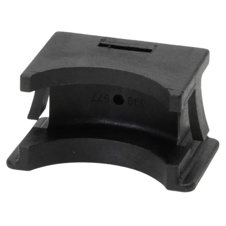
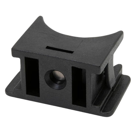
Selden Drum Lockblock & Disc Assembly for 200S Furlers
SEL-SPR-539-577-01
$30.99 USDUnit price /Unavailable -
Selden Drum Line Half (Pair) for 200S Furlers
SEL-SPR-539-557-04
$174.00 USDUnit price /Unavailable -
Selden Lubricating Grease (90 g) - for Furlex, Winches and Furling Masts
SELDEN-LUBRICATING-GREASE-TUBE-90-G
$20.99 USDUnit price /Unavailable -
-
Selden Drum Line Guide Fitting Assembly for 300S Furlers
SEL-SPR-539-260-01
$107.95 USDUnit price /Unavailable -
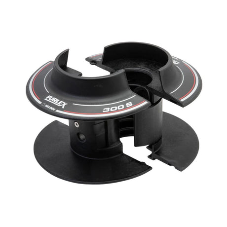
Selden Drum Lockblock & Disc Assembly for 300S Furlers
SEL-SPR-539-277-01
$39.99 USDUnit price /Unavailable -
Selden Tack Swivel Snap Shackle (6mm) for 100S Furlers
SEL-SPR-307-336
$48.99 USDUnit price /Unavailable -
Selden Head Swivel Top Guard for 300S Furlers
SEL-SPR-539-286-01
$30.99 USDUnit price /Unavailable -
Selden Forestay Wire Pack (15.4m - 7mm) for 200S Furlers
SEL-SPR-601-005-62
$325.00 USDList Price: $379.00 USDUnit price /Unavailable -
Selden Intermediate Extrusion Assembly (2.4 m) for 200S Furlers
SEL-SPR-539-565-06
$255.00 USDUnit price /Unavailable -

Selden Connecting Plate 58x11 mm for Furlex 200S/TD/E Foil System
SELDEN-CONNECT-PLATE-58X11F200AL
$16.99 USDUnit price /Unavailable -
Selden Intermediate Extrusion Assembly (2.0 m) for 200S Furlers
SEL-SPR-539-564-01
$184.00 USDUnit price /Unavailable -
Selden Stainless Drum Cover for Furlex 200S
SELDEN-COVER-ASSY-FLX-200S
$130.00 USDUnit price /Unavailable -
Selden LINE GUARD BKT ASSY F200S
SELDEN-LINE-GUARD-BKT-ASSY-F200S
$49.99 USDUnit price /Unavailable -
Selden Tack Swivel Wedge (36mm - 7mm) for 200S Furlers
SEL-SPR-301-153
$32.99 USDUnit price /Unavailable -
Selden Tack Swivel Wedge (33mm - 6mm) for 200S Furlers
SEL-SPR-301-152
$28.99 USDUnit price /Unavailable -
Selden Tack Swivel Socket (7mm) for 200S Furlers
SEL-SPR-301-195
$92.95 USDUnit price /Unavailable -
Selden Head Swivel Assembly for 300S Furlers
SEL-SPR-539-281-01
$1,320.00 USDUnit price /Unavailable -
Selden Head Swivel Assembly for 200S Furlers
SEL-SPR-539-581-01
$1,060.00 USDUnit price /Unavailable -
Selden Extension Link for ø8 and 10 mm Furlex Systems
SELDEN-EXT-LINK-200-204-300-304S-8-10
$148.00 USDUnit price /Unavailable -
Selden Extension Link for ø6 and 7 mm Furlex Systems
SELDEN-EXTENS-FORK-EYEFLX-6-7MMST
$75.95 USDUnit price /Unavailable -
Selden Stemball/eye Toggle with Jaw/jaw Toggle, for ø10 mm Headstays
SELDEN-TOGGLE-STEMBALL-FORK-WIRE-10
$325.00 USDUnit price /Unavailable