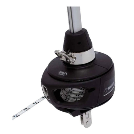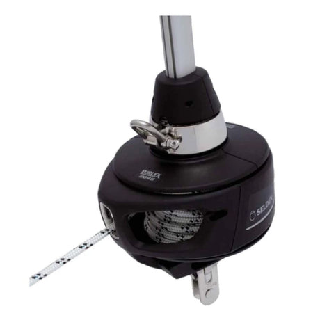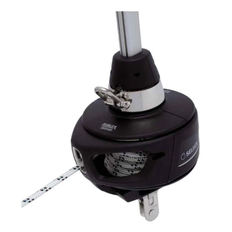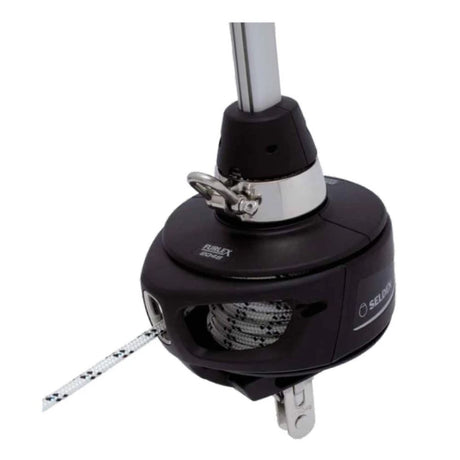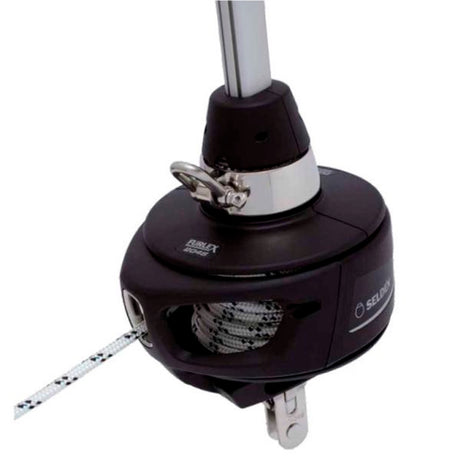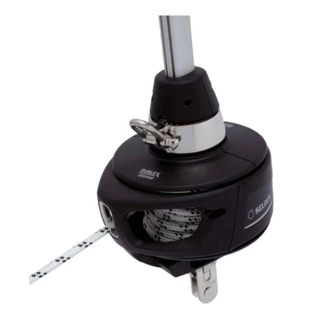




Selden Furlex 204S & 304S — Owner's Manual

Manual and spare parts list for the Selden Furlex 204S and 304S jib furlers (fourth-generation Furlex), with the 304S Ø12 mm supplement, the rod-stay luff assembly and the line-drum hub replacement kit.
Download PDF ▾

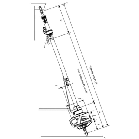
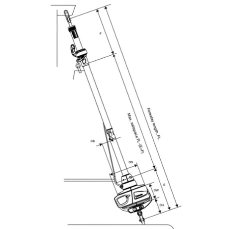
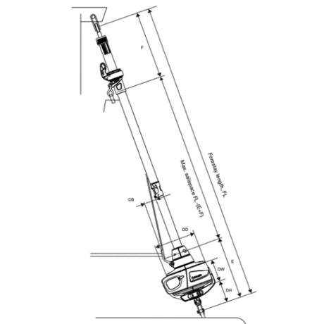
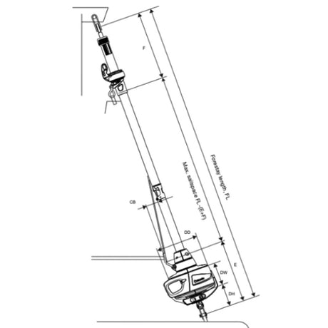
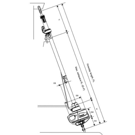
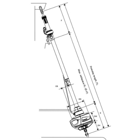
Main Dimensions
Basic pack: drum unit, halyard swivel, furling rope, bearing halves, top guard, sail feeder. Extended pack adds halyard leads, stanchion blocks, pre-feeder pack and Torx bit set. Foil pack and wire/eye pack (swaged stud/eye, or Sta-Lok eye with or without rigging screw) complete the system; rod stays come from the rod manufacturer.
| Furlex | DD | DH | DW | HO | Wire | Pin | TED | TET |
|---|---|---|---|---|---|---|---|---|
| 204S | Ø185 (7 9/32") | 115 (4 17/32") | 90 | 65 (2 9/16") | Ø6 (15/64") | Ø10 (25/64") | Ø12.5 (31/64") | 8.6 (11/32") |
| 204S | Ø185 | 115 | 90 | 65 | Ø7 (9/32") | Ø12 (15/32") | Ø13.5 (17/32") | 9.6 (3/8") |
| 204S | Ø185 | 115 | 90 | 65 | Ø8 (5/16") | Ø14 (35/64") | Ø16.5 (21/32") | 10.6 (27/64") |
| 304S | Ø220 (8 21/32") | 125 (4 59/64") | 105 (4 9/64") | 70 (2 3/4") | Ø8 (5/16") | Ø14 (35/64") | Ø16.5 (21/32") | 10.6 (27/64") |
| 304S | Ø220 | 125 | 105 | 70 | Ø10 (25/64") | Ø16 (5/8") | Ø16.5 (21/32") | 12.6 (1/2") |
| 304S Ø12 (597-626-E) | Ø220 | 160 | 105 | 110 | Ø12 | Ø19 (3/4") | Ø19.5 | 16 (5/8") |
Sail information
| 204S | 304S | |
|---|---|---|
| Head deduction F | 425 (16 3/4"); Mk2 swivel: 485 (19") | Ø8: 430 (17"); Ø10: 530 (21"); Mk2: Ø8 490 (19 1/4"), Ø10 590 (23 1/4") |
| Tack deduction E (add any toggle or link) | Ø6 / Ø7: 265 (10 1/2"); Ø8: 275 (10 3/4") | Ø8: 310 (12 1/4"); Ø10: 315 (12 1/2") |
| Cutback CB | 60 (2 23/64") | 60 (2 23/64") |
| Luff groove internal diameter DLG | Ø6 (15/64") | Ø7 (9/32") |
| Luff groove width WLG | 3.0 (1/8") | 3.0 (1/8") |
| Luff extrusion overall | 35x25 (1 3/8" x 63/64") | 42x31 (1 21/32" x 1 17/32") |
- Max. luff length = FL – (F + E). Use webbing loops at head and tack; a luff tape compatible with the Furlex extrusion is required.
- Halyard-to-forestay angle 10–15°, never less than 10°; at least 50 mm (1 31/32") between halyard swivel and top guard. Sail too short: HMPE or wire pendant fixed to the head.
Wire Length & Top Extrusion Calculation
WL = FL – T – H (H = any extra links or toggles). For a swaged-stud stay, WL is the finished length eye to end of stud, not a cutting length.
| Furlex / stay | T without rigging screw | T with rigging screw | A+B without rigging screw | A+B with rigging screw |
|---|---|---|---|---|
| 204S Ø6 wire | 80 mm (3 5/32") | 165 mm (6 1/2") | 1295 mm (50 63/64") | 1250 mm (49 7/32") |
| 204S Ø7 wire | 80 mm (3 5/32") | 165 mm (6 1/2") | 1320 mm (51 31/32") | 1250 mm (49 7/32") |
| 204S Ø8 wire | 90 mm (3 35/64") | 175 mm (6 57/64") | 1335 mm (52 9/16") | 1270 mm (50") |
| 304S Ø8 wire | 100 mm (3 15/16") | 200 mm (7 7/8") | 1370 mm (53 15/16") | 1290 mm (50 25/32") |
| 304S Ø10 wire | 100 mm (3 15/16") | 205 mm (8 5/64") | 1405 mm (55 5/16") | 1315 mm (51 49/64") |
| 304S Ø12 wire (stud only) | 140 mm (5 1/2") | – | 1520 mm (60") | – |
| 204S Rod -8 / -10 | 80 mm (3 5/32") | 165 mm (6 1/2") | 1255 / 1280 mm | 1210 mm (47 41/64") |
| 204S Rod -12 / -15 | 90 mm (3 35/64") | 175 mm (6 57/64") | 1285 mm (50 19/32") | 1220 mm (48 1/32") |
| 304S Rod -15 | 100 mm (3 15/16") | 200 mm (7 7/8") | 1320 mm (51 31/32") | 1240 mm (48 13/16") |
| 304S Rod -17 | 100 mm (3 15/16") | 205 mm (8 5/64") | 1355 mm (53 11/32") | 1265 mm (49 51/64") |
| 304S Rod -22 | 100 mm (3 15/16") | 205 mm (8 5/64") | 1415 mm (55 45/64") | 1325 mm (52 11/64") |
- N = (WL – (A+B)) / 2400, rounded down; C = N × 2400; top extrusion D = WL – (A+B) – C; top distance tube E = D – X, with X = 200 mm (7 7/8") for 204S and 250 mm (9 27/32") for 304S.
- Example (204S Ø8, rigging screw 50% extended): FL 16.243 – 175 = WL 16.068; (16068 – 1270) / 2400 = 6.16 → N = 6; C = 14400; D = 398; E = 198.
- If D is less than 400 mm: N new = N – 1, C new = N new × 2400 + 2000, D new = D + 400, E new = E + 400 (example: 14000 / 798 / 598). The manual's note gives the limit as 700 mm (27 1/2") while the table footnote says 400 mm (as printed). If D exceeds 2000 mm, cut the top from a 2400 mm extrusion.
- Foil: 1000 mm (39 3/8") bottom extrusion, 2400 mm extrusions and a 2000 mm top extrusion. The luff is assembled on the stay from the top down; distance-tube hinge sideways; push each distance tube in about half a joining sleeve; short distance tube in about 50 mm (1 31/32) at the bottom for the bearing plug halves.
- Rod stays (597-180-E): feed everything from the top, starting with the lower short extrusion, long joining sleeve (204: 260 mm / 304: 325 mm); push the top distance tube 100 mm into the extrusion; secure the bearing halves with the spring pin and lock the upper eye grub screw with adhesive.
- 304S Ø12 (597-626-E): stud stay only; the joining sleeves must be threaded on before the stud is swaged (black 325 mm sleeve lowest, then one 250 mm sleeve per full-length extrusion). Check WL before swaging.
Drum Unit & Deck
- Fit the drum unit over the eye terminal so the flat on the terminal meets the two ribs in the tube shaft; with a rigging screw, align all three flat faces (screw unscrewed halfway). Clevis and split pin through tube shaft and eye.
- Adaptor halves go one way only (knob in the upper hub into the front half); thin bead of locking adhesive on the screw threads, tighten firmly.
- The toggle supplied with the drum unit always goes directly to the chain plate; an extension link needs a toggle between it and the stemhead fitting.
- Below-deck installation: first turning point at least 300 mm (11 13/16") away, system clear of the well sides, avoid deck conduits, well drained.
- Racing: minimum distance forestay attachment to tack 100–125 mm (3 15/16" – 4 59/64").
Furling Line & Halyard
- Fit the line with cover and line guide removed: feed through both drum channels, first screw about 25 mm from the rope end, then push into the jaw slot and fit the second screw.
- Wind about 30 turns; 3–5 turns must remain with the sail fully furled. UV strip to starboard → line exits to port.
- Cockpit turning block working load at least 3000 N (300 kg / 657 lb) for 204S and 5000 N (500 kg / 1125 lb) for 304S; swivel block plus a normal cleat.
- Halyard leads: drill Ø5.3 mm (7/32"), self-tapping M6 screws with grease, 2 screws (204S) / 3 screws (304S). Replace leads at 50% wear.
- Rigging screw: turn only the body, never the wire terminal; tension the forestay with backstay/cap shrouds, not the rigging screw. Split pins opened 20°.
Inspection, Service & Hub Replacement
- Yearly: check the foil and sail grooves, that everything turns freely and that bearings are greased. Remove the brims and grease all four ball bearings in the lower unit (upper and lower main bearings, tack ring bearings); bring the swivel down to the sail feeder and grease both its bearings.
- Wash with fresh water and mild detergent and rinse well; silicone-free polish or wax on the extrusions; protect black plastic when polishing stainless.
- Store with the mast, aluminium away from steel, never wrapped damp in plastic; in frost areas store dry or with centre extrusions raised. Drum unit and halyard swivel slide off for storage.
- Never dismantle the halyard swivel or drum unit (loose balls). Re-making a Sta-Lok: heat the threads to free the adhesive, keep at least 10 mm (25/64") of free wire above the socket, cut strands about 5 mm (13/64") and always use a new wedge.
- Line-drum hub replacement (597-916-E), service kits 549-203-10R (204S), 549-303-10R (304S): remove the 2-turn retaining ring, shim, washer, balls and bearing ring; lift the drum off by the tack ring without lifting the tack-ring assembly; fit the new halves with the join on notch A, four self-tapping screws, then grease the balls and fit a new retaining ring. Kit contents: 2 drum halves, 4 + 2 self-tapping screws, retaining ring, 5 balls, 5 bearing rollers.
Troubleshooting
| Problem | Probable cause | Action |
|---|---|---|
| Sail will not unfurl, or only partly | Halyard wrapped round the foil; furling line jammed; forestay too slack; dirt/salt in bearings; too much halyard tension | Ease halyard and reverse; free the line; tension backstay/cap shrouds or shorten the Furlex; rinse and grease; ease halyard |
| Sail hard to furl | No line on drum; windward sheet not released; free turn not working; large turning angles; line tangled; line guide chafing; swivel upside down | Wind more line; release sheet; rinse and grease; re-route; rewind; adjust the fitting; fit swivel correctly |
| System wobbles | Forestay too loose | Tension backstay and/or cap shrouds |
| Sail unfurls after furling | Furled too loosely; line not belayed | Furl with some drag; belay the line |
| Sail hard to hoist | Luff tape too thick; halyard routing; dirt in groove | Sailmaker; check sheaves; clean the groove |
| Luff cannot be tensioned | Swivel touches top guard; halyard angle too great | Shorten the sail or move the halyard lead up |
| UV strip inside the roll | Line wound the wrong way | Empty the drum, rewind the other way, check 3–5 turns remain |
| Sail wrinkled at tack | Tack ring turned the wrong way before tacking the sail | Rotate the tack ring round the system and re-tack |
Spares & Accessories
| Part No. | Item | Description | Dimension | Fits | |
|---|---|---|---|---|---|
| 549-204-01R | 1 | Adapter assembly, incl. screws | 204S | View part → | |
| 549-304-01R | 1 | Adapter assembly, incl. screws | 304S | View part → | |
| 549-225-01R | 2 | Top guard, incl. screws | 204S | View part → | |
| 549-325-01R | 2 | Top guard, incl. screws | 304S | View part → | |
| 549-223-01R | 3 | Sail feeder, incl. screws | 204S | View part → | |
| 549-323-01R | 3 | Sail feeder, incl. screws | 304S | View part → | |
| 549-219-01R | 4 | Lower bearing | 204S | Ask us to source it → | |
| 549-319-01R | 4 | Lower bearing | 304S | View part → | |
| 549-200-10R | 5 | Lower swivel complete, incl. shackle, clevis pin and split pin | 204S | Ask us to source it → | |
| 549-300-10R | 5 | Lower swivel complete, incl. shackle, clevis pin and split pin | 304S | Ask us to source it → | |
| 549-211-01R | 6 | Lock block | 204S | View part → | |
| 549-311-01R | 6 | Lock block | 304S | View part → | |
| 549-209-10R | 7 | Cover assembly, incl. lock block and screws | 204S | View part → | |
| 549-309-10R | 7 | Cover assembly, incl. lock block and screws | 304S | View part → | |
| 549-207-01R | 8 | Brim assembly, two brims incl. screws | 204S | View part → | |
| 549-307-01R | 8 | Brim assembly, two brims incl. screws | 304S | View part → | |
| 549-242-01R | 9 | Halyard swivel Mk3, incl. shackle | 204S | Ask us to source it → | |
| 549-342-01R | 9 | Halyard swivel Mk3, incl. shackle | 304S | Ask us to source it → | |
| 165-108-01R | 10 | Clevis pin and split pin | 204S | View part → | |
| 165-213-01R | 10 | Clevis pin and split pin | 304S | View part → | |
| 307-021R | 11 | Screw pin shackle | M8x16x32 | 204S, 304S | Ask us to source it → |
| 549-203-10R | 12 | Drum replacement kit | Ø87 | 204S | View part → |
| 549-303-10R | 12 | Drum replacement kit | Ø104 | 304S | View part → |
| 100g~312-501 | 17 | Furlex grease | 204S, 304S | Ask us to source it → | |
| 612-034-12 | 18 | Furling line | Ø8 L=25000 | 204S | View part → |
| 612-035-12 | 18 | Furling line | Ø10 L=28000 | 304S | View part → |
| 538-971-01 | 19 | Stanchion block, 1-pack | For Ø25 | 204S, 304S | View part → |
| 538-210-02R | 20 | Stanchion block | For Ø25/30 | 204S, 304S | View part → |
| 505-538-01R | 21 | Prefeeder pack | 204S, 304S | View part → | |
| 1g~312-305 | 22 | Locking adhesive | 204S, 304S | Ask us to source it → | |
| 614-520R | 23 | Soft shackle | 6 (4) mm | 204S, 304S | View part → |
| 549-221-10R | 24 | Connecting plate kit | 1 long + 6 short | 204S | View part → |
| 549-321-10R | 24 | Connecting plate kit | 1 long + 6 short | 304S | View part → |
| 508-159-03 | 25 | Halyard lead kit (1 lead, 1 insulator, screws, Ø5,3 drill bit) | 204S | Ask us to source it → | |
| 508-128-03 | 25 | Halyard lead kit (1 lead, 1 insulator, screws, Ø5,3 drill bit) | 304S | Ask us to source it → | |
| 155-703 | 26 | Self-tapping screw | MRT TT 6x12 | 204S, 304S | View part → |
Numbers 13–16 are not used in the printed list.

Wire, Eye Fitting & Luff Extrusion Packs
| Part No. | Item | Description | Dimension | Fits | |
|---|---|---|---|---|---|
| 601-004-65 | – | Forestay wire pack | L=13000 | 204S Ø6 | View part → |
| 601-004-66 | – | Forestay wire pack | L=15400 | 204S Ø6 | View part → |
| 601-005-66 | – | Forestay wire pack | L=15400 | 204S Ø7 | View part → |
| 601-005-67 | – | Forestay wire pack | L=17800 | 204S Ø7 | View part → |
| 601-006-78 | – | Forestay wire pack | L=15500 | 204S Ø8, 304S Ø8 | View part → |
| 601-006-79 | – | Forestay wire pack | L=17900 | 204S Ø8, 304S Ø8 | View part → |
| 601-008-65 | – | Forestay wire pack | L=17900 | 304S Ø10 | View part → |
| 601-008-66 | – | Forestay wire pack | L=20300 | 304S Ø10 | View part → |
| 601-008-67 | – | Forestay wire pack | L=22500 | 304S Ø10 | View part → |
| 601-054-65 | – | Forestay compact wire pack | L=13000 | 204S Ø6 | View part → |
| 601-054-66 | – | Forestay compact wire pack | L=15400 | 204S Ø6 | View part → |
| 601-055-66 | – | Forestay compact wire pack | L=15400 | 204S Ø7 | View part → |
| 601-055-67 | – | Forestay compact wire pack | L=17800 | 204S Ø7 | View part → |
| 601-056-78 | – | Forestay compact wire pack | L=15500 | 204S Ø8, 304S Ø8 | View part → |
| 601-056-79 | – | Forestay compact wire pack | L=17900 | 204S Ø8, 304S Ø8 | View part → |
| 601-057-65 | – | Forestay compact wire pack | L=17900 | 304S Ø10 | View part → |
| 601-057-66 | – | Forestay compact wire pack | L=20300 | 304S Ø10 | View part → |
| 601-057-67 | – | Forestay compact wire pack | L=22500 | 304S Ø10 | View part → |
| 174-536-12 | 1 | Rigging screw pack | 204S Ø6 | Ask us to source it → | |
| 174-537-12 | 1 | Rigging screw pack | 204S Ø7 | Ask us to source it → | |
| 174-538-12 | 1 | Rigging screw pack | 204S Ø8 | Ask us to source it → | |
| 174-519-12 | 1 | Rigging screw pack | 304S Ø8 | Ask us to source it → | |
| 174-520-12 | 1 | Rigging screw pack | 304S Ø10 | Ask us to source it → | |
| 301-655-11 | 2 | Eye pack, stud | 204S Ø6 | Ask us to source it → | |
| 301-656-11 | 2 | Eye pack, stud | 204S Ø7 | Ask us to source it → | |
| 301-657-11 | 2 | Eye pack, stud | 204S Ø8 | Ask us to source it → | |
| 301-658-11 | 2 | Eye pack, stud | 304S Ø8 | Ask us to source it → | |
| 301-659-11 | 2 | Eye pack, stud | 304S Ø10 | Ask us to source it → | |
| 301-663-11 | 3 | Eye pack, Sta-Lok | 204S Ø6 | Ask us to source it → | |
| 301-664-11 | 3 | Eye pack, Sta-Lok | 204S Ø7 | Ask us to source it → | |
| 301-665-11 | 3 | Eye pack, Sta-Lok | 204S Ø8 | Ask us to source it → | |
| 301-666-11 | 3 | Eye pack, Sta-Lok | 304S Ø8 | Ask us to source it → | |
| 301-667-11 | 3 | Eye pack, Sta-Lok | 304S Ø10 | Ask us to source it → |
| Part No. | Pack | Forestay length | Furlex | |
|---|---|---|---|---|
| 549-232-02 | Luff extrusion pack (wire Ø6–8) | FL=10550 | 204S | View part → |
| 549-232-03 | Luff extrusion pack (wire Ø6–8) | FL=12950 | 204S | View part → |
| 549-232-04 | Luff extrusion pack (wire Ø6–8) | FL=15350 | 204S | View part → |
| 549-332-02 | Luff extrusion pack (wire Ø8–10) | FL=15500 | 304S | View part → |
| 549-332-03 | Luff extrusion pack (wire Ø8–10) | FL=17900 | 304S | View part → |
| 549-230-01 | Single luff extrusion pack: extrusion L=1000, joining sleeve L=260, distance tube L=860, connecting plate L=122 | 204S | View part → | |
| 549-231-01 | Single luff extrusion pack: extrusion L=2000, joining sleeve L=200, distance tube L=1800, connecting plate L=63 | 204S | View part → | |
| 549-232-06 | Single luff extrusion pack: extrusion L=2400, joining sleeve L=200, distance tube L=2200, connecting plate L=63 | 204S | View part → | |
| 549-330-01 | Single luff extrusion pack: extrusion L=1000, joining sleeve L=325, distance tube L=825, connecting plate L=144 | 304S | View part → | |
| 549-331-01 | Single luff extrusion pack: extrusion L=2000, joining sleeve L=250, distance tube L=1750, connecting plate L=70 | 304S | View part → | |
| 549-332-06 | Single luff extrusion pack: extrusion L=2400, joining sleeve L=250, distance tube L=2150, connecting plate L=70 | 304S | View part → |
Toggles & links
| Part No. | Toggle | Forestay | Length H | Details | |
|---|---|---|---|---|---|
| 174-104-01 | Eye/fork toggle | Ø6 (1/4") | 40 (1 1/2") | Eye D1 11, clevis pin D2 11, fork W2 12 | View part → |
| 174-105-01 | Eye/fork toggle | Ø7 (9/32") | 45 (1 3/4") | Eye D1 13, clevis pin D2 13, fork W2 12 | View part → |
| 174-106-01 | Eye/fork toggle | Ø8 (5/16") | 50 (2") | Eye D1 16, clevis pin D2 15.8, fork W2 12 | View part → |
| 174-107-01 | Eye/fork toggle | Ø10 (3/8") | 65 (2 1/2") | Eye D1 16, clevis pin D2 15.8, fork W2 20 | View part → |
| 517-046-02 | Fork/fork toggle | Ø6 | 40 (1 1/2") | D1 12, W1 11, D2 10, W2 11 | View part → |
| 517-047-02 | Fork/fork toggle | Ø7 | 40 (1 1/2") | D1 12, W1 11, D2 12, W2 12.5 | View part → |
| 517-048-02 | Fork/fork toggle | Ø8 | 50 (2") | D1 14, W1 14, D2 14, W2 15.5 | View part → |
| 517-060-04 | Fork/fork toggle | Ø10 | 55 (2 3/16") | D1 16, W1 14, D2 16, W2 16 | View part → |
| 517-063-01 | Eye/fork extension link | Ø6 / Ø7 | 90 (3 9/16") | D1 12, W1 11, eye 12, gauge W2 6 | View part → |
| 517-062-01 | Eye/fork extension link | Ø8 / Ø10 | 130 (5") | D1 14 (Ø8) / 16 (Ø10), W1 14, eye 16.5, gauge W2 10 | View part → |
Need a part that isn't listed? Ask us to source it and quote the part number from the PDF.
Products in this Manual
-

-

SEL03502564
$2,800.00 USDList Price: $3,612.00 USDUnit price /Unavailable -

-
SEL04203164
$4,350.00 USDList Price: $5,641.00 USDUnit price /Unavailable -
SEL04203163
$4,200.00 USDList Price: $5,433.00 USDUnit price /Unavailable -
SEL04203161
$3,900.00 USDList Price: $5,022.00 USDUnit price /Unavailable -
SEL04203153
$3,800.00 USDList Price: $4,893.00 USDUnit price /Unavailable -
SEL03502565
$2,900.00 USDList Price: $3,758.00 USDUnit price /Unavailable -
Selden Extension Link for ø8 and 10 mm Furlex Systems
SELDEN-EXT-LINK-200-204-300-304S-8-10
$148.00 USDUnit price /Unavailable -
Selden Extension Link for ø6 and 7 mm Furlex Systems
SELDEN-EXTENS-FORK-EYEFLX-6-7MMST
$75.95 USDUnit price /Unavailable -
Selden Jaw-Jaw Toggle for ø8 and 10 mm Wire Application
SELDEN-TOGGLE-FO-FO-W8-10P16-16-W38
$160.00 USDUnit price /Unavailable -
Selden Double Jaw Toggle for ø8 mm Wire Application
SELDEN-TOGGLE-FO-FO-WIRE-O82-PINS
$92.95 USDUnit price /Unavailable -
Selden Jaw-Jaw Toggle for ø7 mm Wire Application
SELDEN-TOGGLE-FO-FO-WIRE-O72-PINS
$91.95 USDUnit price /Unavailable -
Selden Jaw-Jaw Toggle for ø6 mm Wire Application
SELDEN-TOGGLE-FO-FO-O5-6-W30-2-PINS
$61.95 USDUnit price /Unavailable -
Selden Eye-Jaw Toggle for 3/4" Turnbuckle and ø10 mm Wire Applications
SELDEN-TOGGLE-3-4-EYE-FRK16-ASSY
$140.00 USDUnit price /Unavailable -
Selden Eye-Jaw Toggle for 5/8" Turnbuckle and ø8 mm Wire Applications
SELDEN-TOGGLE-5-8-EYE-FRK-ASSY
$50.95 USDUnit price /Unavailable -
Selden Eye-Jaw Toggle for 1/2" Turnbuckle and ø7 mm Wire Applications
SELDEN-TOGGLE-1-2-EYE-FRK-ASSY
$42.99 USDUnit price /Unavailable -
Selden Eye-Jaw Toggle for 7/16" Turnbuckle and ø6 mm Wire Applications
SELDEN-TOGGLE-7-16-EYE-FRK-ASSY
$35.99 USDUnit price /Unavailable -
Selden 2400 mm Luff Section, Furlex 304S/E/TD
SELDEN-FOIL-PACK-FLX-304-L-2400
$235.00 USDUnit price /Unavailable -
Selden 2000 mm Luff Section, Furlex 304S/E/TD
SELDEN-FOIL-PACK-FLX-304-L-2000
$158.00 USDUnit price /Unavailable -
Selden 1000 mm Luff Section, Furlex 304S/E
SELDEN-FOIL-PACK-FLX-304-L-1000
$135.00 USDUnit price /Unavailable -
Selden 2400 mm Luff Section, Furlex 204S/E/TD
SELDEN-FOIL-PACK-FLX-204-L-2400
$194.00 USDUnit price /Unavailable -
Selden 2000 mm Luff Section, Furlex 204S/E/TD
SELDEN-FOIL-PACK-FLX-204-L-2000
$104.95 USDUnit price /Unavailable -
Selden 1000 mm Luff Section, Furlex 204S/E
SELDEN-FOIL-PACK-FLX-204-L-1000
$89.95 USDUnit price /Unavailable