Selden Furlex 404E — Supplementary Manual

Installation, wiring, operation, emergency furling and service of the Selden Furlex 404E / 404TDE electric drive unit, the retrofit packs for 404S, 404TD, 400S and 400TD, and the belt-replacement procedure.
Download PDF ▾

Furlex Electric 404E / 404TDE
This supplementary manual covers the electric drive unit only; the furler itself is installed per the Furlex 404S manual (597-181, above deck) or 404TD manual (597-465, through deck). The drive is compatible with the 404S/404TD (current) and 400S/400TD (discontinued); a converted 400S becomes the 400E MkII and a 400TD the 400TDE MkII. Part and serial numbers are on the gearbox, inside the covers. It is only to be used with Selden's 42V power supply and SEL-Bus system.
- Self-locking worm gear (40:1) in both directions: furl from either side of the boat.
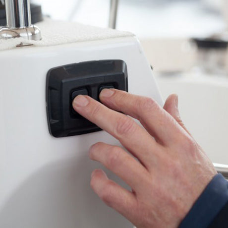
- Two speeds: one button = low speed; press both buttons together for high speed.
- Torque limiting: the controller cuts the motor when current reaches the pre-set level for each Furlex size.
- Emergency operation: ½" socket on the starboard side; emergency line driver included.
- Gear house in anodized aluminium, stainless parts in 316 / 316L; sealed, pressure-tested motor housing.
Technical Specification
Electrical
| Item | Value |
|---|---|
| Input voltage to motor control unit | 42V |
| Peak torque | 135Nm |
| Peak current consumption (@12V battery) | 95A |
| Total gear ratio | 218:1 |
| Low speed (unloaded) | 30 rpm |
| High speed (unloaded) | 50 rpm |
| Efficiency (MCU + drive unit) | 30% |
| Cable size MCU – motor | 6 mm² |
Main dimensions (mm)
| Above deck | Forestay Ø | L | W2 | H | W1 | D1 |
|---|---|---|---|---|---|---|
| 404E | 12 | 285 | 220 | 65 | 21 | 19 |
| 404E | 14 | 290 | 220 | 85 | 23 | 22 |
| Below deck | Forestay Ø | A | F | L1 | L2 | HW | HW1 | W2 | D1 |
|---|---|---|---|---|---|---|---|---|---|
| 404TDE | 12 | 375-540 | 33 | 185 | 135 | 220 | 185 | 22 | 19 |
| 404TDE | 14 | 375-540 | 33 | 185 | 135 | 220 | 185 | 22 | 22 |
| 400TDE MkII | 12 / 14 | 440-630 | 33 | 185 | 135 | 220 | 185 | 22 | 19 |
Basic & Retrofit Packs
Furlex Electric Basic pack: Standard (above deck) – 549-400-20
| Part No. | Included part | |
|---|---|---|
| 549-416-01 | Halyard swivel | Ask us to source it → |
| 549-400-02 | Lower swivel | Ask us to source it → |
| 549-632-01 | Motor unit | Ask us to source it → |
| 319-836 | Protective hose | Ask us to source it → |
| 312-211 | Clip | Ask us to source it → |
| 539-664-01 | Emergency line driver | Ask us to source it → |
| 549-426-01 | Top bearing assy. | View part → |
| 549-440 | Lower bearing fwd | Ask us to source it → |
| 549-441 | Lower bearing aft | Ask us to source it → |
| 549-423-01 | Sail feeder assy | View part → |
| 539-653-01 | Deck gland kit | Ask us to source it → |
| 312-305 | Locking adhesive | View part → |
| 508-128-02 | Halyard U-lead kit | Ask us to source it → |
| 505-538-01 | Pre-feeder pack | View part → |
| 312-501 | Grease | View part → |
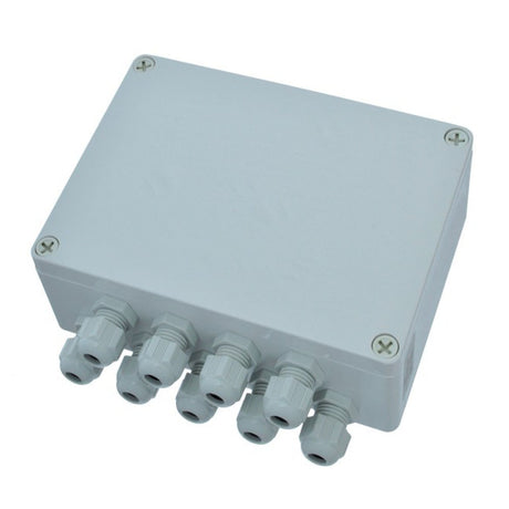
| 532-487-01 | Connection box | Ask us to source it → |
Basic pack: Through Deck (404TDE Ø12 549-470-16 / Ø14 549-470-17)
- Halyard swivel 549-416-01; lower swivel 549-470-12 (Ø12) / 549-470-13 (Ø14); motor unit 549-632-02
- Protective hose 319-836, 2 clips 312-211, emergency line driver 539-664-01
- Torque tube assembly 549-472-02, deck fitting assembly 549-459-01, torque stay with bracket 508-657-02, 2 screws 153-202
- Top bearing assy. 549-426-01, lower bearing fwd 549-440 / aft 549-441, sail feeder assy 549-423-01
- Locking adhesive 312-305, halyard U-lead kit 508-128-02, pre-feeder pack 505-538-01, grease 312-501
Earlier units use the larger gland 539-647, hose 319-837 (Ø30/25) and clips 312-212; deck gland kit 539-647-01 is supplied with these kits.
| Part No. | Retrofit pack | Forestay | |
|---|---|---|---|
| 549-632-265 | Furlex Electric retrofit pack for Furlex 404S | Ø12 mm | View part → |
| 549-632-270 | Furlex Electric retrofit pack for Furlex 404S | Ø14 mm | View part → |
| 549-632-215 | Furlex Electric retrofit pack for Furlex 400S (1997-2014) | Ø12 mm | View part → |
| 549-632-220 | Furlex Electric retrofit pack for Furlex 400S (1997-2014) | Ø14 mm | View part → |
| 549-632-240 | Furlex Electric retrofit pack for Furlex 400TD (1997-2019) | Ø12 & Ø14 mm | View part → |
| 549-632-290 | Furlex Electric retrofit pack for Furlex 404TD (2020-) | Ø12 & Ø14 mm | View part → |
- 404S retrofit: motor unit 549-632-01, hub 539-791-01, 2 washers 164-459, 5 balls 539-128, 5 bearing rollers 319-937, retaining ring 301-569, hose, clips, deck gland kit, emergency line driver, toggle 539-783-01 / 539-784-01, connection box.
- 400S retrofit: motor unit 549-632-03, 2 carriers 539-782, hose, clips, deck gland kit, emergency line driver, toggle 539-783-01 / 539-784-01, connection box.
- 400TD retrofit: motor unit 549-632-04, 2 carriers 539-782, 2 screws MC6S 12x20 153-020. 404TD retrofit: motor unit 549-632-02, hub 539-791-01, 2 screws MP6SS 12x25 153-202. Both: hose, clips, emergency line driver, torque stay with bracket 508-657-02, locking adhesive, grease.
Motor Unit Installation
Above deck (404E / 404S retrofit)
- Check space (anchor work); extension links are available for more clearance below the unit.
- The forestay attachment must take the torque load: use only the Furlex Electric torque toggle and optional extension link (dimensions below).
- 404S retrofit: remove the drum unit from the stay. Remove circlip, washer, balls and ball-bearing ring without lifting the line drum (the top main bearing would open). Wiggle off the line drum, grease the rollers, slide on the new hub. Refit with the new circlip; if axial play exceeds 0.5mm fit shim 164-459 between washer and circlip. Never re-use the circlip.
- Slide the swivel over the terminal, fit the adaptor halves, then fit the motor unit so the bronze gear engages the carriers in the hub. The motor unit can be turned 90° to suit the forestay fitting; fit clevis pin and split pin, then toggle and optional link.
Through deck (404TDE / TD retrofits)
- Leave space for the emergency line driver. The TDE forestay attachment is not designed for the torque load: a torque stay from the bracket on the housing to the side of the hull is required (without it the forestay fitting may break). Maximum working load on the torque bracket: 3800N.
- Turn the centre shaft via the upper toggle until its holes align with one of the four holes in the holder; check the two locking screws fit.
- Fit the swivel without the motor unit and set the tack-ring-to-deck-fitting gap to approx. 5 mm at the front (eye of tack ring pulled up). The 404TDE has no locking nut.
- Fit swivel through deck fitting and motor unit, fit the two locking screws with locking adhesive, then clevis pin and split pin.
- Bond the torque bracket to the hull on the port side, perpendicular to the drive unit, with a structural adhesive. Mark the torque stay, drill ø6.5mm for the clevis pin and cut off the excess leaving => 10mm of material beyond the hole.
- 400TD retrofit: fit the carriers, holder H and insulator (45° mounting possible), locking adhesive on all eight screws; adjust the 5 mm gap with the bronze nut D.
Torque Toggle & Extension Link (above deck)
| Part No. | Type | Forestay | Length H | Clevis pins D1 / D2 | Widths | |
|---|---|---|---|---|---|---|
| 539-783-01 | Furlex Electric torque toggle (fork/fork) | Ø12 mm | 65 | Ø19 / Ø19 | W1 20 / W2 21 | View part → |
| 539-784-01 | Furlex Electric torque toggle (fork/fork) | Ø14 mm | 80 | Ø22 / Ø22 | W1 21 / W2 23 | View part → |
| 517-072-01 | Extension link | Ø12 mm | 190 | Ø19 / eye 19.5 | W1 20 / thickness 19.2 / internal 38 | Ask us to source it → |
| 517-073-01 | Extension link | Ø14 mm | 190 | Ø22 / eye 22.5 | W1 21 / thickness 20.2 / internal 44.3 | Ask us to source it → |
Dimensions in mm.
Optional Parts
| Part No. | Optional part | Fits | |
|---|---|---|---|
| 517-117-01 | Extension link, forestay Ø12, L=190mm | 404E, 400E MkII | View part → |
| 517-118-01 | Extension link, forestay Ø14, L=190mm | 404E, 400E MkII | View part → |
| 164-523 | Shims for toggle, forestay Ø12 mm | 404E, 400E MkII | Ask us to source it → |
| 164-524 | Shims for toggle, forestay Ø14 mm | 404E, 400E MkII | Ask us to source it → |
| 533-922 | Short crank, emergency, L=100 mm | all four models | Ask us to source it → |
| 533-923 | Long crank, emergency, L=325 mm | all four models | Ask us to source it → |
| 532-827-01 | SEL-Bus Converter (for custom control buttons) | all four models | Ask us to source it → |
| 540-461-01 | Panel, 1 push button | all four models | Ask us to source it → |
| 540-462-01 | Panel, 2 push buttons | all four models | Ask us to source it → |
| 532-487-01 | Connection box / cable glands (included by default in Furlex E above deck) | 404E, 400E MkII | Ask us to source it → |
| 549-633-01R | Belt replacement kit (belt 549-633), 404E/TDE | 404E, 404TDE | Ask us to source it → |
Belt kit 549-633-01R is from the belt-replacement sheet 597-621-E.
Electrical Installation
- Installation by a person with marine installation skills; system switched off for any installation or service. Never alter the rated amperage of overcurrent protective devices or leave the boat unattended with the Furlex Electric energized.
- Above deck: route the cables through the protective hose, drill a ø20-30mm hole in the deck, bed the deck gland in sealant and fix it with the self-tapping screws. Clamp the hose to drive unit and gland (do not over-tighten).
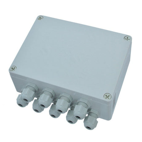
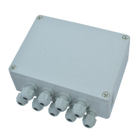
- Mount the connection box as high as possible in the anchor box, with a drip loop in the cables. It has sealing inserts for three cables on each side (assembly instruction 597-919-E inside the box).
- Through deck: form a loop in the cables, mark the lowest point and drill a ø8mm drain hole there in the hose.
- Connect the cables to MCU contacts L1, L2, L3 (grey, brown, orange) for standard anti-clockwise furling. For the opposite direction, swap orange to L2 and brown to L1.
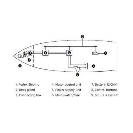
- Power supply (converts 12/24V to 42V), MCU, push buttons and SEL-Bus cables are sold separately; three 5 m connection cables come with the drive unit.
Operation & Emergency Furling
Normal operation
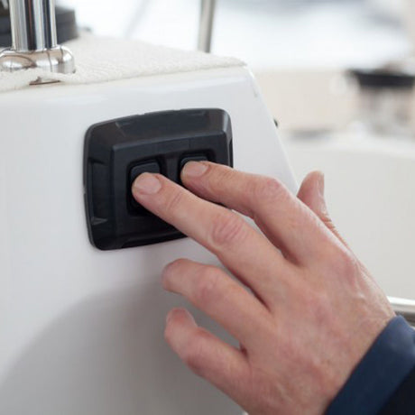
- Control current must be on (except emergency). Push IN or OUT for low speed; hold the first button and press the second for high speed.
- Unfurl: release the windward sheet, one turn of the leeward sheet on a winch, push OUT and gradually tension the sheet; go back to low speed just before fully out.
- Furl: keep light resistance on the leeward sheet; close hauled gives the best wind angle.
- Never use Furlex Electric for sheeting. Use a furling jib cover when leaving the boat.
Emergency furling
- Switch the electric power off.
- Insert the line driver in the ½" socket (starboard side) and turn the knob clockwise.
- Pull the endless line to rotate the furler, or use the emergency crank.
- Remove the line driver or crank before switching power back on: it will rotate rapidly in normal operation.
Troubleshooting
| Problem | Probable cause | Action |
|---|---|---|
| Furlex not operating | Electric failure or bad connection | Furl with the emergency line driver, then troubleshoot the electric system (manual 597-275) and look for corroded or loose wires in the connection box |
| Stops when heavily loaded | Overload | Ease the load; the controller limits torque by cutting current. Check for friction using the emergency winding system |
| Excessive friction | Salt, dirt, lack of grease | Rinse, clean and lubricate per the furler manual |
| Runs in wrong direction | Wires not properly installed | Connect per the colour codes; to reverse, swap any two of the three motor cables |
| Motor runs, luff does not turn | Belt worn or broken | Remove the port cover, inspect and replace the belt |
| Oil leakage | Defective seals or broken housing | Contact a Selden service point |
Service & Belt Replacement
Maintenance
- Frequently: rinse with fresh water (including a TDE in the anchor box) and check the anchor-box drainage.
- Yearly: check the lower swivel turns freely and the worm gear works (emergency handle); check for oil or grease leaks; protect bronze with anti-corrosion spray; grease the swivel bearings; inspect hose, connection box and cables.
- Every 5th year (more often for charter and long-distance use): motor-unit service by an authorized Selden dealer – cleaning, new seals, re-greasing of gear and bearings.
- Warranty: 2 years.
Replacing the belt, 404E/TDE (597-621-E)
Belt 549-633, kit no. 549-633-01R. Tools: Torx T30, hex key 6mm, flat screwdriver 6-8mm, grease, thread-locking adhesive.
- Rinse the drive unit, remove the port-side cover and discard the seal; wipe the sealing surfaces.
- Loosen motor screws (1) and (2) about 1/2 a turn to release belt tension; remove the belt.
- Fit the new belt, lever the screwdriver in recess (3) against the housing to tension it, lock with screw (2). The belt should move ~1-2mm. Tighten screws (1) and (2) hard.
- Grease both sides of the new seal, seat it in the housing recess, fit the cover with locking adhesive on the screws; tighten evenly 1/2-3/4 turn past finger-tight. Do not over-tighten.
Need a part that isn't listed? Ask us to source it and quote the part number from the PDF.
Products in this Manual
-


Selden Lubricating Grease (90 g) - for Furlex, Winches and Furling Masts
SELDEN-LUBRICATING-GREASE-TUBE-90-G
$20.99 USDUnit price /Unavailable -

-
Selden Control Pack (No Buttons) for 400e / 404e Furlers
SEL53281568
$790.00 USDUnit price /Unavailable -
Selden Control Pack (Genoa) for 400e / 404e Furlers
SEL53281566
$970.00 USDUnit price /Unavailable -
Selden Control Pack (Cutter) for 400e / 404e Furlers
SEL53281567
$970.00 USDUnit price /Unavailable -
Selden Locking Adhesive for Stalok Terminals
SELDEN-LOCKING-ADHESIVE-1ML
$23.99 USDUnit price /Unavailable -
Selden SAIL FEEDER ASSY, FLX 404
SELDEN-SAIL-FEEDER-ASSY-FLX-404
$101.95 USDUnit price /Unavailable -
-
Selden Torsional Rigid Jaw-jaw Toggle for ø14 mm Furlex 400/404 Electric
SELDEN-TOGGLE-FLX-400-404E-14MM
$415.00 USDUnit price /Unavailable -
Selden Torsional Rigid Jaw-jaw Toggle for ø12 mm Furlex 400/404 Electric
SELDEN-TOGGLE-FLX-400-404E-12MM
$345.00 USDUnit price /Unavailable -
Selden Extension Link for ø14 mm Furlex Electric Systems
SELDEN-EXT-LINK-FLX-400E-404E-14MM
$685.00 USDUnit price /Unavailable -
Selden Extension Link for ø12 mm Furlex Electric Systems
SELDEN-EXT-LINK-FLX-400E-404E-12MM
$600.00 USDUnit price /Unavailable -
Selden Furlex Conversion Kit - 404 to 404e (12 / 14mm Wire)
SEL549632290
$8,440.00 USDUnit price /Unavailable -
Selden Furlex Conversion Kit - 400 to 400e (TD) (12 / 14mm Wire)
SEL549632240
$7,500.00 USDUnit price /Unavailable -
Selden Furlex Conversion Kit - 400 to 400e (14mm Wire)
SEL549632220
$7,670.00 USDUnit price /Unavailable -
Selden Furlex Conversion Kit - 400 to 400e (12mm Wire)
SEL549632215
$7,630.00 USDUnit price /Unavailable -
Selden Furlex Conversion Kit - 404 to 404e (14mm Wire)
SEL549632270
$7,990.00 USDUnit price /Unavailable -
Selden Furlex Conversion Kit - 404 to 404e (12mm Wire)
SEL549632265
$7,970.00 USDUnit price /Unavailable -
SEL05203810
$13,200.00 USDUnit price /Unavailable -
SEL05203825
$10,600.00 USDUnit price /Unavailable -
SEL05203809
$12,900.00 USDUnit price /Unavailable -
SEL05203824
$10,400.00 USDUnit price /Unavailable -
SEL05203823
$10,400.00 USDUnit price /Unavailable -
SEL05203808
$12,700.00 USDUnit price /Unavailable