



Selden Furlex Electric 200E, 300E & 400E — Owner's Manual

Technical data, torque and toggle requirements, electrical installation (cables, fuses, battery, control box, remote control), operation, emergency furling, service and belt replacement for the Selden Furlex Electric 200E, 300E and 400E (and TDE) drive units.
Download PDF ▾

Furlex Electric 200E / 300E / 400E
Discontinued model – documents and spare parts as printed.
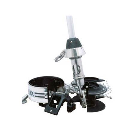
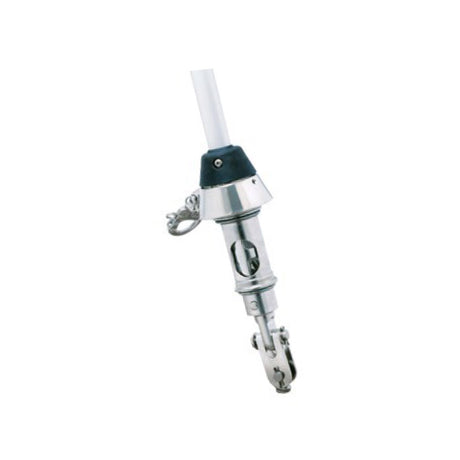
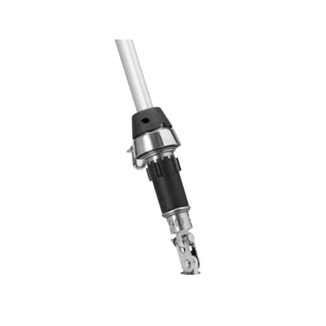
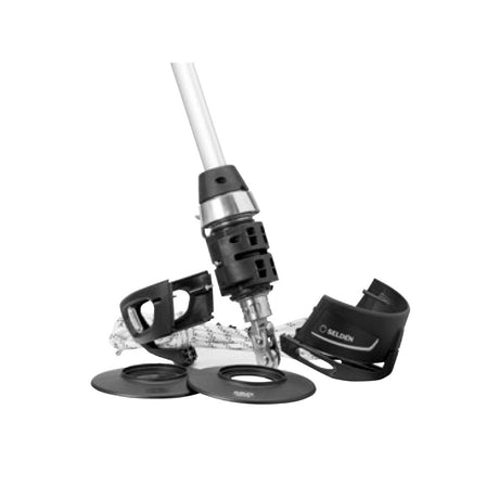
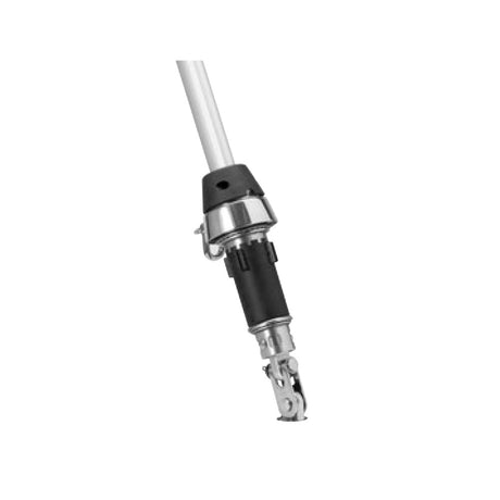
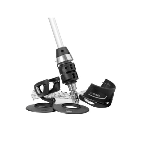
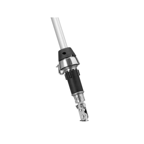
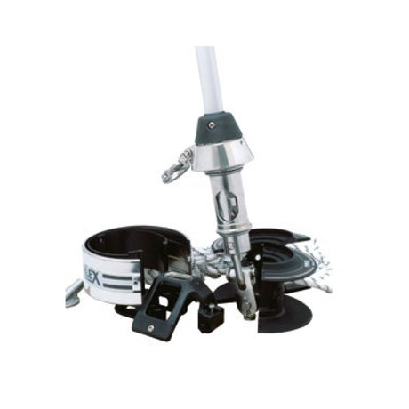
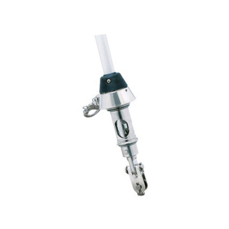
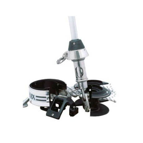
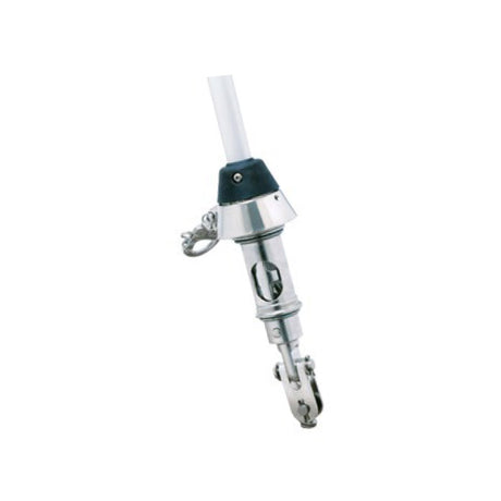
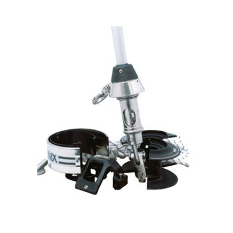
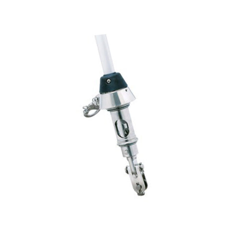
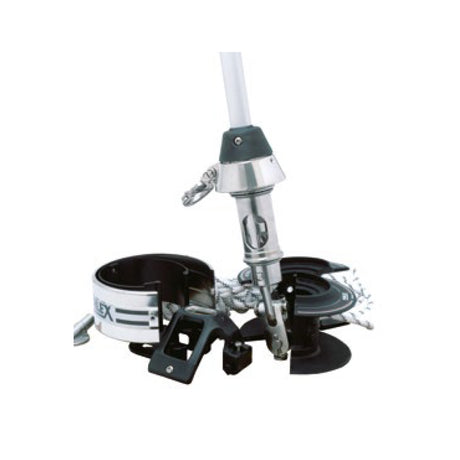
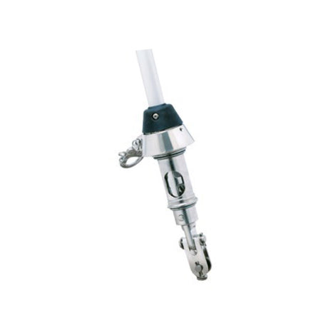
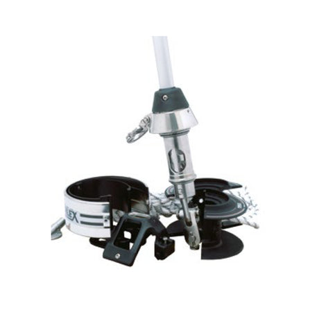
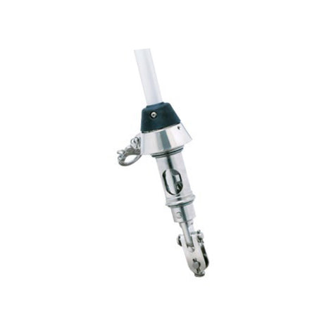
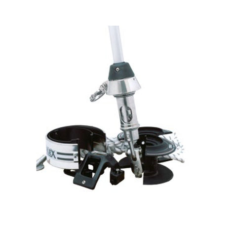
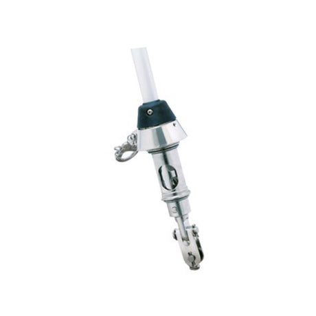
The drive unit is the motor unit fitted to a Furlex S or TD lower bearing assembly (Furlex S from 1997 can be retrofitted). The furler itself is installed per the manual for the base model (595-104-E 200S & 300S, 595-231-E 200TD & 300TD, 595-116-E 400S, 595-240-E 400TD). The size designation is on the motor unit. Guarantee on Furlex Electric parts: 2 years.
Technical Data
Motor & gear
| Furlex | Voltage (V) | Nominal power (W) | Motor speed unloaded (rpm) | Motors | Total ratio | Belt ratio | Reduction gear |
|---|---|---|---|---|---|---|---|
| 200E | 12 | 220 | 2330 | 1 | 53.4:1 | 1.78:1 | 30:1 |
| 300E | 12/24 | 450 | 2150 | 1 | 60.8:1 | 1.52:1 | 40:1 |
| 400E | 12/24 | 900 | 2150 | 2 | 63.1 | 1.5:1 | 42:1 |
Key facts
- Motor unit IP57; DC brush motor with neodym magnets, direction reversed by a relay in the control box.
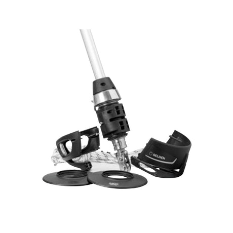
- Belt drive (toothed aluminium pulleys, composite belt) under the port cover; motor under the starboard cover.
- Self-locking worm and bronze pinion: the sail cannot unfurl however hard the sheet load. ½" socket on the starboard side for emergency furling.
- The 60, 90 and 135 Nm loads (200E / 300E / 400E) correspond to furling in very hard weather or with the sheet insufficiently slack; in normal conditions the unit works at 20 to 30% of capacity. Torque, current and speed curves: diagrams 1.3.a–1.3.e in the PDF.
- Not for continuous operation under high load: do not furl and unfurl repeatedly in heavy conditions.
Dimensions, Torque & Toggles
Drive unit (mm)
| Deck mounted | L | H2 | H3 | HW | HW1 |
|---|---|---|---|---|---|
| 200E | 225 | 45 | 60 | 160 | 145 |
| 300E | 260 | 65 | 80 | 210 | 160 |
| 400E | 314 | 135 | 159 | 218 | 203 |
| Through deck | A | F | L1 | L2 | HW | HW1 |
|---|---|---|---|---|---|---|
| 200TDE | 290-450 | 20 | 145 | 95 | 160 | 145 |
| 300TDE | 330-490 | 20 | 170 | 105 | 210 | 160 |
| 400TDE | 433-633 | 30 | 190 | 131 | 218 | 203 |
The black collar on the 300TD motor unit is chamfered to give F = 20 mm.
Forestay attachment torque (Max Service Load, Nm)
| Furlex | Wire | Masthead | Partial | Toggle width B |
|---|---|---|---|---|
| 200E | 6 mm | 95 | 108 | 32 |
| 200E | 7 mm | 144 | 168 | 35 |
| 200E | 8 mm | 219 | 226 | 35 |
| 300E | 8 mm | 242 | 281 | 35 |
| 300E | 10 mm | 430 | 440 | 40 |
| 400E | 12 mm | 758 | 801 | 47 |
| 400E | 14 mm | 1141 | 998 | 47 |
With no furling line, all torsion goes through the drive unit, toggle and any link to the boat's forestay attachment, which must not deform locally. Existing standard toggles and links must be replaced by the stiff Furlex E types. If the chainplate is too weak, a boat-specific torque absorber can be fitted to the four threaded holes under the motor unit.
| Part No. | Type | Forestay | H | D1 | W1 | D2 | W2 | W3 | |
|---|---|---|---|---|---|---|---|---|---|
| 539-658-01 | Stiff toggle | Ø 6 | 45 | 12 | 10.2 | 10 | 12 | View part → | |
| 539-659-01 | Stiff toggle | Ø 7 | 45 | 12 | 10.2 | 12 | 14 | View part → | |
| 539-660-01 | Stiff toggle | Ø 8 | 55 | 14 | 13.6 | 14 | 14 | View part → | |
| 539-667-01 | Stiff toggle | Ø 10 | 55 | 16 | 13.6 | 16 | 16 | View part → | |
| 539-783-01 | Stiff toggle | Ø 12 | 65 | 19 | 20 | 19 | 21 | View part → | |
| 539-784-01 | Stiff toggle | Ø 14 | 80 | 22 | 21 | 22 | 23 | View part → | |
| 517-070-01 | Extension link | Ø 6 / Ø 7 | 90 | 12 | 10.2 | eye 12.5 | thk 10 | 27 | Ask us to source it → |
| 517-071-01 | Extension link | Ø 8 / Ø 10 | 130 | 16 | 13.7 | eye 16.5 | thk 13.5 | 33 | Ask us to source it → |
| 517-072-01 | Extension link | Ø 12 | 190 | 19 | 20 | eye 19.5 | thk 19.2 | 38 | Ask us to source it → |
| 517-073-01 | Extension link | Ø 14 | 190 | 22 | 21 | eye 22.5 | thk 20.2 | 44.3 | Ask us to source it → |
Dimensions in mm (D = rigging bolt / eye diameter, W = fork width or thickness, W3 = internal width). A raised drive unit must still connect to the boat via the Furlex toggle; split pins opened 20°. Keep the anchor box well drained – especially for a TDE.
Kit Parts & Accessories
| Part No. | Item | Model | |
|---|---|---|---|
| 539-630 | Carriers (2 per kit) | 200E | Ask us to source it → |
| 539-648 | Carriers (2 per kit) | 300E | Ask us to source it → |
| 539-782 | Carriers (2 per kit) | 400E | Ask us to source it → |
| 319-845-01 | Ball bearings in cage (retrofit) | 200E | Ask us to source it → |
| 319-846-01 | Ball bearings in cage (retrofit) | 300E | Ask us to source it → |
| 301-510 | Locking ring (retrofit) | 200E | Ask us to source it → |
| 301-508 | Locking ring (retrofit) | 300E | Ask us to source it → |
| 319-836 | Protective cable sleeve (+ 312-211) | 200E | Ask us to source it → |
| 319-837 | Protective cable sleeve (+ 312-210, 2 hose clamps) | 300E / 400E | Ask us to source it → |
Control package: control box 12V or 24V (check the dataplate), connection box, 15 m signal cable 7x0.75 mm², deck collar with 4 self-tapping screws (not TDE), GENOA IN / OUT buttons if ordered, instructions. Halyard leads: 200S 508-159 (4 screws), 300S/400S 508-128 (6 screws), drill bit Ø 5.3 mm.
| Part No. | Accessory | Note | |
|---|---|---|---|
| 531-033-15 | 15m signal cable 7x0.75 mm², colour coded | Ask us to source it → | |
| 540-459-01 | Control button GENOA OUT | Ask us to source it → | |
| 540-460-01 | Control button GENOA IN | Ask us to source it → | |
| 540-461-01 | Stainless panel for control buttons, single | Ask us to source it → | |
| 540-462-01 | Stainless panel for control buttons, double | Ask us to source it → | |
| 532-510-01 | Complete remote control MK1 (hand unit with battery + plug-in receiver board) | control box software up to FW1.7.0 | Ask us to source it → |
| 532-460-01 | Extra hand unit for remote control, incl. battery, MK1 | up to FW1.7.0 | Ask us to source it → |
| 532-465-01 | Receiving card, plug-in type | MK1, MK2 | Ask us to source it → |
| 532-460-11 | Extra hand unit for remote control, incl. battery, MK2 | FW2.0.0 and 4-function receiver | Ask us to source it → |
| 532-466-10 | Receiving box for remote control (4 functions) | MK2 transmitter; spare fuse glass tube 4 A (T4L250V) | Ask us to source it → |
| 517-070-01 | Eye/fork extension link Ø 6, Ø 7 mm, L=90 mm | Ask us to source it → | |
| 517-071-01 | Eye/fork extension link Ø 8, Ø 10 mm, L=130 mm | Ask us to source it → | |
| 517-072-01 | Eye/fork extension link Ø 12 mm, L=190 mm | Ask us to source it → | |
| 517-073-01 | Eye/fork extension link Ø 14 mm, L=190 mm | Ask us to source it → | |
| 164-516 | Shims, Ø 6, Ø 7, Ø 8 mm wire | Ask us to source it → | |
| 164-519 | Shims, Ø 10 mm wire | Ask us to source it → | |
| 164-523 | Shims, Ø 12 mm wire | Ask us to source it → | |
| 164-524 | Shims, Ø 14 mm wire | Ask us to source it → | |
| 532-514 | Switch, toggle type, long neck, rubberised (max 7 mm panel) | Ask us to source it → | |
| 532-512 | Fuse holder (fuse not included) | Ask us to source it → | |
| 532-513 | Blade fuse 160 A | 200E 12V, 300E 12/24V; min. cable 16 mm² | Ask us to source it → |
| 533-922 | Short crank for emergency furling, L=100 mm | Ask us to source it → | |
| 533-923 | Long crank for emergency furling, L=325 mm | Ask us to source it → |
Electrical Installation
Components & battery
- Battery → main fuse and isolator → control box (C1) → connection box (C2) → drive unit (C3). Avoid the engine starter battery.
- Battery capacity at least 115 Ah for 200E/300E/400E 12V, at least 60 Ah for 300E/400E 24V.
- Control box (H=250, W=180 Depth=105, IP65) upright on a dry bulkhead below deck, cable entries down, never in the anchor box. Control-current glass fuse Ø 5x20 3.15 A. At 110 A 12 V (75 A 24 V) current is cut within 1 sec; the factory-set potentiometers must not be adjusted.
- Connection box (IP65, 130 x 130 x 77 mm, plinths up to 35 mm2) in the anchor box close to the deck collar; strip C2/C3 12 mm, crimp collars on C3. C3 is 6mm2 (200E) or 16 mm2 (300E/400E); keep it under 1.5 m.
- Deck collar: hole saw Ø 20-25 mm, 4 self-tapping screws (L=19 mm, torx T25).
- Control buttons IP67: Ø 30 mm hole saw direct in laminate (max 5), or Ø 37 mm with the stainless panel. A control-current switch and a button-lighting switch must be fitted.
- If the extrusion turns the wrong way, swap C3's wires in the connection box (not the signal wires).
Cables & fuses
Minimum fuse: 200/300E 12V = 125 A; 300E 24V = 60 A; 400E 12V = 150 A; 400E 24V = 80 A.
| C1 cross-section | Max. fuse |
|---|---|
| 16 mm2 | 160 A |
| 25 mm2 | 200 A |
| 35 mm2 | 315 A |
| 50 mm2 | 400 A |
| 70 mm2 | 500 A |
| Max. length C1+C2 (one conductor) | 200E/300E 12V | 200E/300E 24V | 400E 12V | 400E 24V |
|---|---|---|---|---|
| 16 mm2 | 3.8 m | 8 m | 2.5 m | 7 m |
| 25 mm2 | 6 m | 12 m | 3.8 m | 11 m |
| 35 mm2 | 8 m | 16 m | 5.4 m | 15 m |
| 50 mm2 | 12 m | 24 m | 7.5 m | 22 m |
| 70 mm2 | – | – | 11 m | 30 m |
C4: 15 m tinned 7 x 0.75 mm2 cable (3 wires buttons, 2 lighting, 2 control-current switch). C5: 4 wires x 0.75 mm2. Remote hand unit battery: 6 V type 4LR44, about 25 operating hours; replace each season. Channels 434,33MHz / 433,92MHz.
Operation & Emergency Furling
Furling & unfurling
- Unfurl: control current on, free the windward sheet, one turn of the lee sheet on a winch, hold GENOA OUT while pulling the sheet (upwind is best).
- Furl: free the windward sheet, keep one turn on the winch and ease while holding GENOA IN so the sail rolls firmly. If the motor cuts out, release the button, slacken the sheet and press again – the cut-out is a warning that the load is too high.
- Switch the control current off afterwards. Do not use Furlex E to sheet with.
Emergency furling
- Turn off the control current.
- Fit the emergency unit's square drive into the ½" socket on the starboard side and secure it with the screw/plastic knob (M6 thread).
- Pull the short continuous line, or use a ½" crank (L=100 mm or 325 mm).
- Never leave the emergency gear or crank connected when operating electrically: it would rotate very rapidly.
Care, Service & Belt Replacement
Care & service
- Every week: rinse with fresh water (also a TDE in the anchor box); check the anchor-box drain.
- Every year: check toggle wear, grease lower bearing and halyard swivel with Furlex grease (see the base-model manual, chap. 15); inspect sleeve, cables C3 and connection box; new remote battery.
- Every 5th year (more often for charter / long-distance): dealer service of the reduction gear (lithium grease SKF LGEP 2/04) – seals, O-rings, drive belt.
- Storage: remove the drive unit for dry, ventilated storage, hose ends down; never in a tight package. If left on the extrusion with the mast, support it on a board (it is much heavier than a Furlex S unit). A TDE can winter onboard with the anchor-box cover open.
Changing the belt (595-526-E)
- Disconnect power. Remove the port-side cover with a torx screwdriver (cut the sealant with a sharp knife).
- Loosen the four screws of the motor with oblong holes slightly (torx T30), push it to its forward position and pull the belt off the unflanged wheel(s).
- Fit the new belt starting at the flanged wheel; lever the motor back with a screwdriver to tension, tighten the motor screws to 10 Nm. The belt should move 2-3 mm by finger force – over-tightening damages the motor bearings.
- Remove all old sealant, run new Loctite 5926 all round the cover groove and both sides of the screw holes, tighten the cover screws to 6 Nm.
| Part No. | Belt replacing kit | |
|---|---|---|
| 539-633-01 | Furlex 200E | View part → |
| 539-651-01 | Furlex 300E | View part → |
| 539-776-01 | Furlex 400E | View part → |
Fault Tracing
With a control button pressed, check the voltage at the connection box, then at the control-box output and input, then the main fuse.
| Finding | Probable cause | Action |
|---|---|---|
| Voltage at connection box OK, motor runs | Broken drive belt | Contact a Selden service point / order the belt kit |
| Voltage at connection box OK, motor does not run | Electric motor out of order | Check cables; if OK, motor service |
| No voltage downstream | Cables faulty or connectors loose/corroded | Clean and tighten connections, replace damaged cables |
| Control-box output not OK, fuse on circuit board blown | Fuse | Replace once; if it persists, contact Selden service |
| Fuse OK, contactor gets voltage | Contactor out of order | Service / spare parts |
| Fuse OK, contactor gets no voltage | Circuit board or control buttons faulty | Service / spare parts |
| Main fuse blown | Fuse undersized or fault | Check the fuse size; have a boat electrician investigate |
Need a part that isn't listed? Ask us to source it and quote the part number from the PDF.
Products in this Manual
-


Selden Furlex Conversion Kit - 300 to 300e (10mm Wire)
SEL549601220
$3,350.00 USDUnit price /Unavailable -

Selden Extension Link for ø14 mm Furlex Electric Systems
SELDEN-EXT-LINK-FLX-400E-404E-14MM
$685.00 USDUnit price /Unavailable -
Selden Extension Link for ø12 mm Furlex Electric Systems
SELDEN-EXT-LINK-FLX-400E-404E-12MM
$600.00 USDUnit price /Unavailable -
Selden Extension Link for ø8 and 10 mm Furlex Electric Systems
SELDEN-EXT-LINK-FLX-200E-204E-300E-304E-8-10MM
$260.00 USDUnit price /Unavailable -
Selden Extension Link for ø6 and 7 mm Furlex Electric Systems
SELDEN-EXTENS-LINK-FLX-204E-6-7MM
$128.00 USDUnit price /Unavailable -
Selden BELT AT3/267/10 (300E) COMP
SELDEN-BELT-AT3-267-10-300E-COMP
$144.00 USDUnit price /Unavailable -
Selden BELT AT3/252/10 (200E) COMP
SELDEN-BELT-AT3-252-10-200E-COMP
$144.00 USDUnit price /Unavailable -
Selden Furlex Conversion Kit - 400 to 400e (TD) (12 / 14mm Wire)
SEL549632240
$7,500.00 USDUnit price /Unavailable -
Selden Furlex Conversion Kit - 400 to 400e (14mm Wire)
SEL549632220
$7,670.00 USDUnit price /Unavailable -
Selden Furlex Conversion Kit - 400 to 400e (12mm Wire)
SEL549632215
$7,630.00 USDUnit price /Unavailable -
Selden Furlex Conversion Kit - 300 to 300e (TD) (8mm / 10mm Wire)
SEL549601240
$3,350.00 USDUnit price /Unavailable -
Selden Furlex Conversion Kit - 300 to 300e (8mm Wire)
SEL549601215
$3,350.00 USDUnit price /Unavailable -
Selden Furlex Conversion Kit - 200 to 200e (TD) (6mm / 7mm / 8mm Wire)
SEL549601225
$3,230.00 USDUnit price /Unavailable -
Selden Furlex Conversion Kit - 200 to 200e (8mm Wire)
SEL549601210
$3,230.00 USDUnit price /Unavailable -
Selden Furlex Conversion Kit - 200 to 200e (7mm Wire)
SEL549601205
$3,230.00 USDUnit price /Unavailable -
Selden Furlex Conversion Kit - 200 to 200e (6mm Wire)
SEL549601200
$3,230.00 USDUnit price /Unavailable -
Selden CTRL PACK FLX 400TDE,EX.SW.24V
SELDEN-CTRL-PACK-FLX-400TDE-EX-SW-24V
$2,860.00 USDUnit price /Unavailable -
Selden CTRL PACK FLX 400TDE, SW. 24V
SELDEN-CTRL-PACK-FLX-400TDE-SW-24V
$3,350.00 USDUnit price /Unavailable -
Selden CTRL PACK FLX 400E EX. SW.24V
SELDEN-CTRL-PACK-FLX-400E-EX-SW-24V
$2,930.00 USDUnit price /Unavailable -
Selden CTRL PACK FLX 400E WITH SW.24V
SELDEN-CTRL-PACK-FLX-400E-WITH-SW-24V
$3,380.00 USDUnit price /Unavailable -
Selden CTRL PACK FLX 400TDE,EX.SW.12V
SELDEN-CTRL-PACK-FLX-400TDE-EX-SW-12V
$2,860.00 USDUnit price /Unavailable -
Selden CTRL PACK FLX 400TDE, SW. 12V
SELDEN-CTRL-PACK-FLX-400TDE-SW-12V
$3,350.00 USDUnit price /Unavailable -
Selden CTRL PACK FLX 400E EX. SW.12V
SELDEN-CTRL-PACK-FLX-400E-EX-SW-12V
$2,930.00 USDUnit price /Unavailable -
Selden CTRL PACK FLX 400E WITH SW.12V
SELDEN-CTRL-PACK-FLX-400E-WITH-SW-12V
$3,380.00 USDUnit price /Unavailable