



Selden GX Furling System — Owner's Manual

Sizing, anti-torsion cable length calculation, line-lock terminal assembly, endless line fitting and operation for the Selden GX7.5, GX10, GX15 and GX25 top-down gennaker furlers and the GX tack adapter for a CX lower swivel, plus the Adjustable Tack Swivel instructions.
Download PDF ▾

GX Systems at a Glance
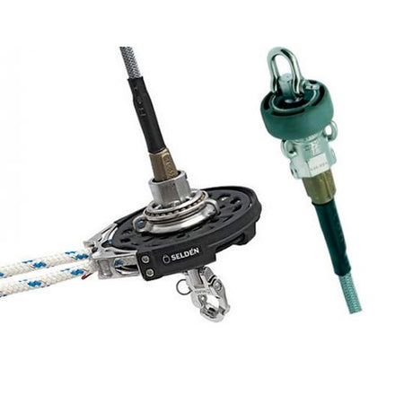
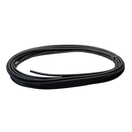
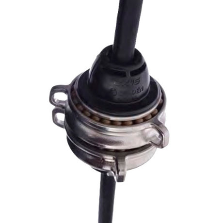
GX is a top-down furler for gennakers / asymmetric spinnakers without an anti-torsion cable sewn into the luff. The head goes on the halyard swivel, the tack on the freely rotating tack ring of the lower swivel, and the luff flies free. Turning the drum, the rigid anti-torsion (AT) cable turns the halyard swivel so the head furls first and the sail rolls tightly from top to bottom. Glass-filled polyamide and stainless steel; the line driver has 14 aluminium teeth; bearings are sealed and maintenance-free – rinse with fresh water, dry, and stow (ideally with the sail).
GX basic kits
| Art. No. | System | Drum Ø (mm) | Safe working load (kN) | Max suggested sail area | Endless line | |
|---|---|---|---|---|---|---|
| 545-018-10 | GX7.5 | 105 | 7.5 | 50 m² | Ø8 mm | View part → |
| 545-118-10 | GX10 | 120 | 10 | 80 m² | Ø8 mm | View part → |
| 545-218-10 | GX15 | 150 | 15 | 115 m² | Ø10 mm | View part → |
| 545-418-10 | GX25 | 190 | 25 | 200 m² | Ø12 mm | View part → |
GX tack adapter for a Selden CX lower swivel (basic kit incl. halyard swivel)
| Art. No. | System | Safe working load (kN) | Max suggested sail area | Compatible CX system | |
|---|---|---|---|---|---|
| 545-028-10 | GX7.5 adapter | 7.5 | 50 m² | CX10 | View part → |
| 545-128-10 | GX10 adapter | 10 | 80 m² | CX15 | Ask us to source it → |
| 545-228-10 | GX15 adapter | 15 | 115 m² | CX25 | Ask us to source it → |
| 545-428-10 | GX25 adapter | 25 | 200 m² | CX40/CX45 | View part → |
Endless line: 16/16 braid/braid polyester. A longer endless line works better – residual friction in the line being pulled forward helps it engage fully in the line driver. Normally led aft to the cockpit; a short loop can be worked on the foredeck.
Calculating the AT-Cable Cutting Length (ATL) and Max Sail Space (MSS)
| System | SDL (mm) | SDH (mm) | LS (mm) | HS (mm) | A (mm) | B (mm) | AT-cable Ø (mm) |
|---|---|---|---|---|---|---|---|
| GX7.5 | 100 | 70 | 100 | 70 | 120 | 120 | 8 |
| GX10 | 105 | 70 | 110 | 70 | 120 | 120 | 11 |
| GX15 | 115 | 80 | 120 | 75 | 120 | 120 | 13 |
| GX25 | 155 | 100 | 155 | 95 | 150 | 150 | 15 |
SDL / SDH = deduction for lower / halyard swivel; LS / HS = lower / halyard swivel length; A / B = addition for the line-lock terminal at the lower / halyard swivel.
GX tack adapter on a CX lower swivel
| Adapter Art. No. | System | AS adapter deduction (mm) | E CX lower swivel deduction (mm) | SDA sail deduction adapter (mm) | |
|---|---|---|---|---|---|
| 545-028-01 | GX7.5 adapter – CX10 | 30 | 115 | 35 | Ask us to source it → |
| 545-128-01 | GX10 adapter – CX15 | 30 | 125 | 35 | Ask us to source it → |
| 545-228-01 | GX15 adapter – CX25 | 40 | 155 | 40 | Ask us to source it → |
| 545-428-01 | GX25 adapter – CX45 (same values for CX40) | 45 | 190 | 50 | Ask us to source it → |
AT-cable length (ATL)
- ID: measure from the halyard shackle (hoisted all the way up to the block, sheave or halyard lead) to the attachment on deck / bowsprit.
- − SD standard deduction (recommended): GX7.5 & GX10 = 100 mm, GX15 & GX25 = 150 mm → TS total system length.
- − HS and − LS (with the tack adapter: − HS, − AS, − E), − any tack-adjustment system, − any other deductions → ATS max space for the AT-cable.
- − 1% for elongation of the Selden AT-cable (ATS × 0,01) → CRL cover length (this is NOT the cutting length).
- + B (line-lock terminal, halyard swivel) + A (line-lock terminal, lower swivel) → ATL AT-cable cutting length.
Max sail space (MSS)
- TS (ID − SD), as above.
- − any tack-adjustment system, − any other deductions, − the same 1% elongation deduction.
- − SDH and − SDL (with the tack adapter: − SDH, − SDA, − E) → MSS, max sail space including space for lashing.
The elongation figure applies to the Selden AT-cable; for other brands use their maker's data. SD gives clearance at sheaves, blocks and leads plus an assembly tolerance.
Assembling the Line-Lock Terminals
Both swivels have line-lock terminals, designed for Selden AT-cables. Assemble them one at a time and don't cut the AT-cable until the first terminal is finished. Terminal parts: base, hub, bronze washer, jaws, O-ring, socket, shrink hose.
- Mark the AT-cable with thin tape in three places, using the dimensions from the calculation (A, CRL, B).
- Dismantle the line-lock terminal.
- Remove the O-ring from the jaws. Feed the heat-shrink hose, socket and O-ring onto the AT-cable.
- Remove the outer cover: cut with scissors at the base, leave the tape in place.
- Cut the inner cover carefully along the cable with a utility knife, avoiding the core (small damage here is acceptable). A vise makes it easier – let the clamping jaw guide the blade.
- Push the inner core against the cable to loosen the tightly packed strands.
- Peel the inner cover off the core and cut it at the base.
- Divide the core strands evenly into 3 groups and tape the 3 ends.
- Cut the centre composite rod at the tape level; remove the tape at the base.
- Feed each core group into the hole at the bottom of a jaw, placing the jaws OVER the outer cover.
- Distribute the jaws evenly and lock them with the O-ring in the groove near the bottom of the jaws; the cover end should be hardly visible. The jaws must squeeze the outer cover when the terminal is screwed together.
- Pull the three strand groups equally and tape them in position.
- Push the socket down onto the jaws / strands.
- Remove the tape from step 12, pull the three groups evenly while pressing the socket down hard (flat-nose pliers help); tap the jaws into the socket with a hammer.
- Place the bronze washer in the bottom of the hub.
- Fit the assembly to the swivel socket and tighten the terminal hard. Back off until the socket groove aligns with the grub screws, apply locking adhesive and tighten the grub screw.
- Cut the residual strands. Shrink the heat-shrink hose over the socket with a heat gun without melting the cable cover (high-quality or vulcanizing tape also works).
Fitting the Endless Line
- Pull the red lanyard and remove the wedge-shaped divider. Rotate until the notches in the stainless line guard and the line driver align.
- Feed the endless line through the line guide and up through the central notch.
- Holding one side in the line-driver notch, rotate a full circle with the driver; the line must stay in the notch (slight compression is normal).
- Remove twists or kinks and refit the divider wedge.
Removing the line is the reverse sequence.
Adjusting the Line Guide
To keep deflection minimal where the line enters the driver, the line guide turns through 360° in 4 × 90° steps: loosen set screw (B) a few turns, rotate the guide, then apply locking adhesive and tighten the set screw into hole (C) in the shaft until it bottoms out. Do not over-tighten.
The lower unit is supplied without locking adhesive on the set screw – apply it even if no adjustment is needed.
Operation
- Attaching the sail: head to the halyard swivel, not lashed too tight – the sail must be free to turn 180° when furling. Tack line to the tack ring of the lower swivel, adjustable for the correct luff shape for furling.
- Hoisting: hoist and tension with a winch; the AT-cable must not be loose during furling.
- Unfurling: slacken the endless line completely and pull the sheet. If the system starts unfurling at speed, do not use the endless line as a brake.
- Furling: keep the AT-cable tensioned – a loose cable corkscrews and furls badly. The forward loop must stay on the line-driver teeth throughout. Lock both ends of the endless line against accidental unfurling (Selden tandem block PBB50 fiddle twin-cam 405-001-40R).
- Always furl in the same direction to keep the AT-cable in good condition.
| Art. No. | Description | |
|---|---|---|
| 405-001-40R | Tandem block PBB50 fiddle twin-cam (locks the endless line) | View part → |
Adjustable Tack Swivel (ATS) – GX7.5 to GX25
The ATS sits on the AT-cable and gives a floating tack: tack adjustability while keeping the sail furlable. On a new system fit it before the AT-cable is connected to the GX line-lock; it can also be retrofitted.
Rigging & operation
- Tack of the sail to the upper swivel ring with the included tack line (relatively close fit).
- Tack control line to the loop on the lower swivel ring, opposite the knots (a snap shackle is recommended), led through a lead or block just aft of the GX lower swivel so it can stay rigged on deck. Size it for a winch and your stopper / cam cleat.
- Furling: AT-cable tensioned hard; pull the tack control line and tack to the lowest position; furl as per the GX manual.
- Unfurling: AT-cable tensioned hard; tack control line connected, tensioned and secured; unfurl as per the GX manual.
Mounting
New system: remove the two grub screws one by one, apply the enclosed locking adhesive and refit; slide the ATS onto the AT-cable rounded top up, screws down; continue the GX assembly.
- Retrofit: unscrew the two locking screws on the GX lower swivel that secure the AT-cable socket, and unscrew the socket / AT-cable.
- Remove the two ATS grub screws and the sleeve halves.
- Feed the ATS hub over the socket / cable, refit the sleeve halves (rounded top up, screw holes down) and lock them with the grub screws and adhesive.
- Refit the socket / cable to the lower swivel, tighten hard, back off until the groove aligns with the locking screws, apply adhesive and tighten.
- If the heat-shrink cover was damaged, wrap a few turns of high-quality tape.
Need a part that isn't listed? Ask us to source it and quote the part number from the PDF.
Products in this Manual
-


Selden Stanchion Mounts - Plain Bearing Block w/ Twin-Cams - 50.0 mm Fiddle
SEL40500140R
$149.00 USDUnit price /Unavailable -
SEL-545-018-21
$1,170.00 USDList Price: $1,516.00 USDUnit price /Unavailable -
SEL-545-218-22
$2,430.00 USDList Price: $3,127.00 USDUnit price /Unavailable -
Selden Furlers - Anti-Torsion Cable for CX10, CX15 & GX7.5 - Dia: 3/8 in (9 mm) - 42.7 ft (13 m)
SEL61302001
$265.00 USDList Price: $307.00 USDUnit price /Unavailable -

SEL61101118
$138.00 USDUnit price /Unavailable -
SEL61100709
$80.95 USDUnit price /Unavailable -
Selden Adjustable Tack Swivel Height Adapter for GX7.5 Furlers
SEL54504010
$280.00 USDList Price: $327.00 USDUnit price /Unavailable -

SEL61101119
$166.00 USDUnit price /Unavailable -
SEL61100708
$98.95 USDUnit price /Unavailable -
SEL61100707
$65.95 USDUnit price /Unavailable -

Selden Line Guard Assembly, CX15/GX10
SELDEN-LINE-GUARD-ASSY-CX15-GX10
$100.95 USDUnit price /Unavailable -
SEL-545-118-22
$1,780.00 USDList Price: $2,303.00 USDUnit price /Unavailable -
SEL-545-118-21
$1,700.00 USDList Price: $2,206.00 USDUnit price /Unavailable -
Selden Furlers - Anti-Torsion Cable for CX25 & GX15 - Dia: 1/2 in (13 mm) - 62.3 ft (19 m)
SEL61302202
$790.00 USDList Price: $917.00 USDUnit price /Unavailable -
Selden Furlers - Anti-Torsion Cable for CX10, CX15 & GX10 - Dia: 3/7 in (11 mm) - 72.2 ft (22 m)
SEL61302104
$615.00 USDList Price: $718.00 USDUnit price /Unavailable -
Selden Free Tack Adapter from CX40 to GX25 Furlers
SEL54542811
$505.00 USDList Price: $587.00 USDUnit price /Unavailable -
Selden Free Tack Adapter from C25 to GX15 Furlers
SEL54522811
$375.00 USDList Price: $437.00 USDUnit price /Unavailable -
Selden Adjustable Tack Swivel Height Adapter for GX10 Furlers
SEL54514010
$340.00 USDList Price: $392.00 USDUnit price /Unavailable -
Selden Free Tack Adapter from CX15 to GX10 Furlers
SEL54512811
$325.00 USDList Price: $379.00 USDUnit price /Unavailable -
SEL61101106
$88.95 USDUnit price /Unavailable -
Selden Twin-Cam Block with Endless Furling Line, ø12 mm / 2x17000 mm, 16 Plait Polyester, Grey/Black
SELDEN-TW-CAM-BLOCK-ENDLESS-O12-2X17M
$495.00 USDUnit price /Unavailable -
Selden Twin-Cam Block with Endless Furling Line, ø12 mm / 2x12000 mm, 16 Plait Polyester, Grey/Black
SELDEN-TW-CAM-BLOCK-ENDLESS-O12-2X12M
$415.00 USDUnit price /Unavailable -
Selden Twin-Cam Block with Endless Furling Line, ø12 mm / 2x9000 mm, 16 Plait Polyester, Grey/Black
SELDEN-TW-CAM-BLOCK-ENDLESS-O12-2X9M
$370.00 USDUnit price /Unavailable -
Selden Twin-Cam Block with Endless Furling Line, ø10 mm / 2x15000 mm, 16 Plait Polyester, Grey/Black
SELDEN-TW-CAM-BLOCK-ENDLESS-O10-2X15M
$320.00 USDUnit price /Unavailable