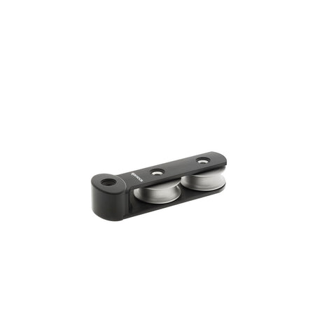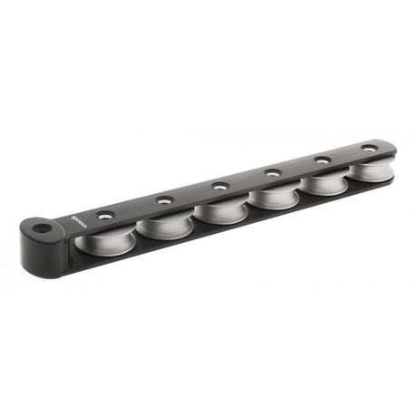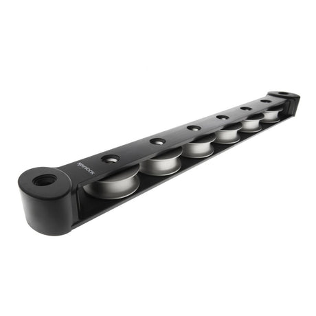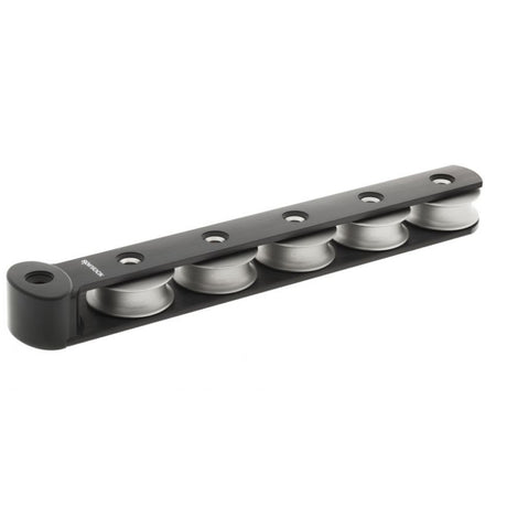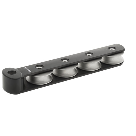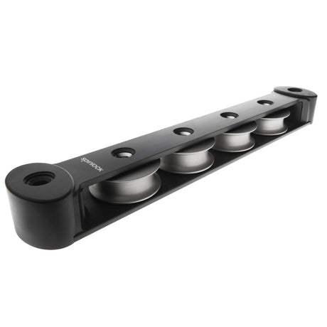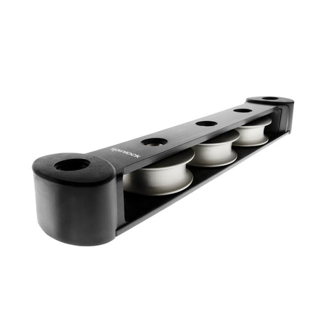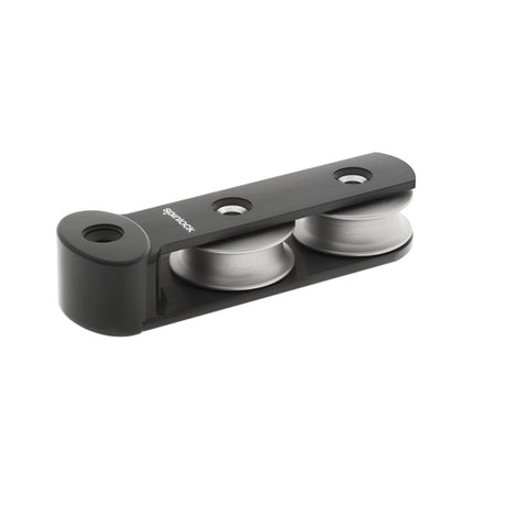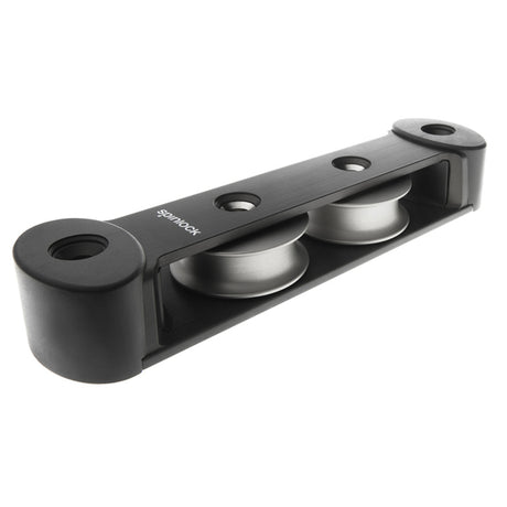




Spinlock TC50 Deck Organiser — Instructions

Layout rules, hole size, fasteners, loads by deflection angle and lengths for the Spinlock TC50 high-load deck organisers with 50 mm alloy sheaves, TC50/2 to TC50/6, Y versions and the double-stacked D versions.
Download PDF ▾

Installation
- Plan the deck layout before marking out holes.
- Keep the vertical rope-entry angle under 10°.
- Install the organiser on an imaginary line bisecting the angle of the rope lead.
- Make sure the deck is flat and has the required strength.
- Drill holes ø8.5mm or 11/32".
- Seal the deck joint with a silicone rubber sealant.
- Insert the flush-fitting countersunk fasteners before fixing to the deck; for maximum safety use A4/70 or A4/80 high-tensile fasteners, M8 CSK head, DIN7991.
Fasteners and Use
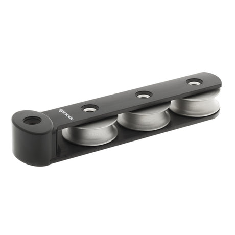
- Each organiser needs a fastener through each sheave and one at each end: a 3-sheave TC50/3 needs 5 fasteners, or 4 for the asymmetric TC50/3Y.
- Check the loading effect of the installed deflection angle, taking account of any unequal deflection angles.
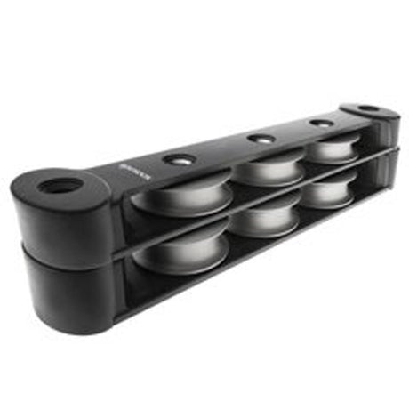
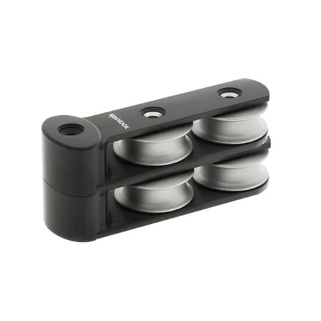
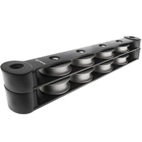
- Double stacked: always use the lower sheaves for the most highly loaded lines. The TC50/4D is a TC50/4 with a T50/4 stacked on top (313.00 long, 59.50 high).
The fastener table in the instructions gives "M8 (1/4")" (as printed).
Models and Loads
| Model | Length (mm) | M8 CSK fasteners | Weight | Total SWL per unit | |
|---|---|---|---|---|---|
| TC50/2 | 201 | 4 | 555g | 1500kg | View part → |
| TC50/2Y | 155 | 3 | 445g | 1500kg | View part → |
| TC50/3 | 257 | 5 | 730g | 2250kg | View part → |
| TC50/3Y | 211 | 4 | 620g | 2250kg | View part → |
| TC50/4 | 313 | 6 | 900g | 3000kg | View part → |
| TC50/4Y | 267 | 5 | 790g | 3000kg | View part → |
| TC50/5 | 369 | 7 | 1080g | 3750kg | View part → |
| TC50/5Y | 323 | 6 | 970g | 3750kg | View part → |
| TC50/6 | 425 | 8 | 1250g | 4500kg | View part → |
| TC50/6Y | 379 | 7 | 1140g | 4500kg | View part → |
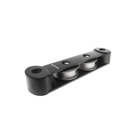
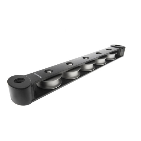
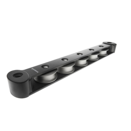
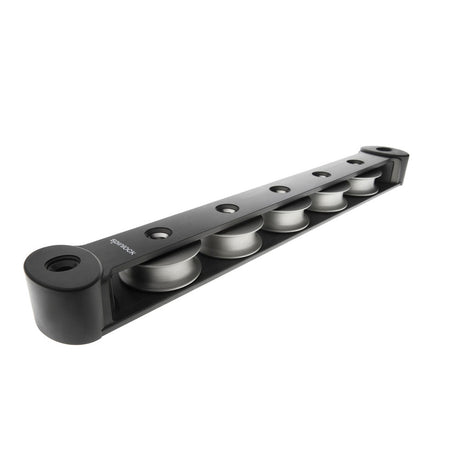
All TC50: Ø50 anodised aluminium sheaves with a composite bearing, on 56 mm centres; 52 mm wide, 33 mm high; max line size Ø14mm; SWL per sheave 1500kg.
Max Rope Tension by Deflection Angle
| Rope deflection angle ‘A’ | Max rope tension (kg) |
|---|---|
| 10° | 8610 |
| 15° | 5750 |
| 30° | 2900 |
| 45° | 1960 |
| 60° | 1500 |
| 90° | 1060 |
- ‘A’ is the angle the rope is deflected by the sheave, measured for a straight or a bisected rope entry.
- The same table is printed on every TC50 drill guide.
Use and Maintenance
- The stainless-steel axle works with the countersunk fasteners for a high-strength, low-weight build.
- Flush regularly with fresh water; when dry, apply a silicone spray or Spinlock grease.
- Do not use mineral oil or solvent-based lubricants such as "WD40": the wrong lubricant degrades the bearing properties.
- Do not let a loaded halyard touch the metal body.
- Tensioned line must bear only on a sheave.
Drill Guides
- One page per model, TC50/2 to TC50/6Y, drawn at 1:2 on A4 – not 1:1.
- Spinlock's warning: if you use a guide as a drill template, set the printer for the drawing scale and always check the dimensions before drilling.
Safety
- Check the product is correctly specified for your application, load and line size, and that it is correctly installed before its first use under load.
- Braided fibre rope only – never three-strand or wire rope. Never use the product if it is damaged or worn, or with damaged rope.
- Never use cleaning or lubricating solvents, polysulphide or polyurethane based sealants: they degrade the product. Do not modify any part.
Need a part that isn't listed? Ask us to source it and quote the part number from the PDF.
Products in this Manual
-


Spinlock Deck Organizer - 3 Sheaves TC50 Symmetric Double Stack (High Load) - Dia: 2 in (50 mm)
SPI-TC50-3D
$464.95 USDList Price: $547.00 USDUnit price /Unavailable -
Spinlock Deck Organizer - 4 Sheaves TC50 Asymmetric Double Stack (High Load) - Dia: 2 in (50 mm)
SPI-TC50-2DY
$374.85 USDList Price: $441.00 USDUnit price /Unavailable -
Spinlock Deck Organizer - 4 Sheaves TC50 Symmetric Double Stack (High Load) - Dia: 2 in (50 mm)
SPI-TC50-2D
$374.85 USDList Price: $441.00 USDUnit price /Unavailable -
Spinlock Deck Organizer - 5 Sheaves TC50 Symmetric (High Load) - Dia: 2 in (50 mm)
SPI-TC50-5
$413.95 USDList Price: $487.00 USDUnit price /Unavailable -
Spinlock Deck Organizer - 3 Sheaves TC50 Asymmetric (High Load) - Dia: 2 in (50 mm)
SPI-TC50-3Y
$307.49 USDList Price: $361.75 USDUnit price /Unavailable -
Spinlock Deck Organizer - 8 sheaves TC50 Asymmetric Double Stack (High Load) - Dia: 2 in (50 mm)
SPI-TC50-4DY
$572.48 USDList Price: $673.50 USDUnit price /Unavailable -
Spinlock Deck Organizer - 8 sheaves TC50 Symmetric Double Stack (High Load) - Dia: 2 in (50 mm)
SPI-TC50-4D
$572.48 USDList Price: $673.50 USDUnit price /Unavailable -
Spinlock Deck Organizer - 6 Sheaves TC50 Asymmetric Double Stack (High Load) - Dia: 2 in (50 mm)
SPI-TC50-3DY
$464.95 USDList Price: $547.00 USDUnit price /Unavailable -
SPI-TC50-2DM
$469.63 USDList Price: $552.50 USDUnit price /Unavailable -
Spinlock Deck Organizer - 12 Sheaves TC50 Asymmetric Double Stack (High Load) - Dia: 2 in (50 mm)
SPI-TC50-6Y
$466.01 USDList Price: $548.25 USDUnit price /Unavailable -
Spinlock Deck Organizer - 6 Sheaves TC50 Symmetric (High Load) - Dia: 2 in (50 mm)
SPI-TC50-6
$466.01 USDList Price: $548.25 USDUnit price /Unavailable -
Spinlock Deck Organizer - 5 Sheaves TC50 Asymmetric (High Load) - Dia: 2 in (50 mm)
SPI-TC50-5Y
$413.95 USDList Price: $487.00 USDUnit price /Unavailable -
Spinlock Deck Organizer - 4 Sheaves TC50 Asymmetric (High Load) - Dia: 2 in (50 mm)
SPI-TC50-4Y
$366.78 USDList Price: $431.50 USDUnit price /Unavailable -
Spinlock Deck Organizer - 4 Sheaves TC50 Symmetric (High Load) - Dia: 2 in (50 mm)
SPI-TC50-4
$366.78 USDList Price: $431.50 USDUnit price /Unavailable -
Spinlock Deck Organizer - 3 Sheaves TC50 Symmetric (High Load) - Dia: 2 in (50 mm)
SPI-TC50-3
$307.49 USDList Price: $361.75 USDUnit price /Unavailable -
Spinlock Deck Organizer - 2 Sheaves TC50 Asymmetric (High Load) - Dia: 2 in (50 mm)
SPI-TC50-2Y
$238.85 USDList Price: $281.00 USDUnit price /Unavailable -
Spinlock Deck Organizer - 2 Sheaves TC50 Symmetric (High Load) - Dia: 2 in (50 mm)
SPI-TC50-2
$238.85 USDList Price: $281.00 USDUnit price /Unavailable